
Fixed grate and incineration system applying same

A technology for fixing grate and grate, applied in the field of incineration system, can solve the problems of incinerator manufacturer's influence on production interests, affecting incineration efficiency, poor ventilation of main combustion chamber, etc., to improve incineration efficiency, ensure incineration temperature, ensure constant and controllable effect

Inactive Publication Date: 2015-05-06
安徽盛燃焚烧炉科技有限公司
View PDF5 Cites 5 Cited by
  • Summary
  • Abstract
  • Description
  • Claims
  • Application Information

AI Technical Summary

Problems solved by technology

At the same time, due to the large amount of dust and granular slag that is inevitably accompanied by traditional garbage before and after incineration, it often blocks the ventilation holes opened on it when moving down along the burning surface of the above-mentioned inclined fixed grate, resulting in poor ventilation in the main combustion chamber. , affecting its incineration efficiency, resulting in frequent shutdowns for cleaning and maintenance of the incinerator, which has been continuously incinerated all year round, which has a huge impact on the actual production benefits of incineration manufacturers

Method used


Image

  • Fixed grate and incineration system applying same
  • Fixed grate and incineration system applying same
  • Fixed grate and incineration system applying same

Examples


Embodiment Construction

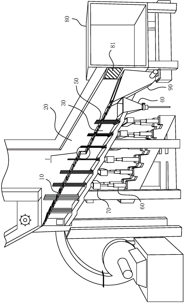
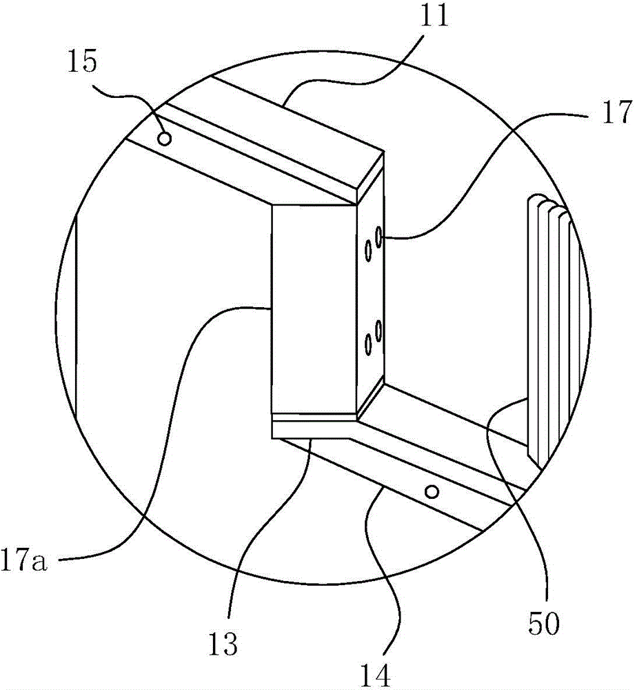
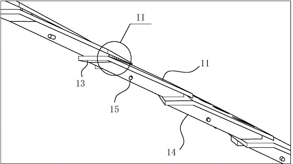
[0038] For ease of understanding, combined here Figure 1-7 The specific implementation structure of the present invention is further described as follows:

[0039] The actual structure of the present invention is as Figure 1-7 As shown, it includes a main combustion chamber arranged in the furnace body, and the main combustion chamber is divided into a combustion chamber 20 and a hot air chamber 30 by a fixed fire grate 10 . Wherein the hot air chamber 30 realizes its air supply function by an external fan, and achieves the air supply and incineration effect on the materials in the combustion chamber 20 through the ventilation holes 12 on the fixed fire grate 10 . The fixed grate 10 can be regarded as composed of a plurality of grate units arranged side by side in sequence along the material traveling direction. Each grate unit includes a rectangular grate plate 11 arranged obliquely on the plate surface and an extension plate 13 fixed on the edge of the upper plate of the...


PUM


Abstract

The invention belongs to the field of waste incineration equipment and particularly relates to a fixed grate and an incineration system applying the same. The fixed grate at least comprises grate plates; the arrangement heights of the grate plates are gradually reduced so as to form a step type grate body structure of the fixed grate; a spacing is formed between plate bodies of each two adjacent grate plates in the perpendicular direction so as to form a ventilation pore running through a grate body; the grate plates are provided with extending plates; the plate faces of each extension plate and the plate body of the previous grate plate are crossed mutually to form a wind guide port structure. The incineration system comprises a main combustion chamber, the fixed grate and a grate ejector rod, wherein the main combustion chamber is isolated and divided into a combustion cavity and a hot blast cavity by the fixed grate; the air inlet end of the hot blast cavity is also the feed end of the fixed grate; the grate ejector rod is used for overturning and ejecting materials on the incineration face; the grate ejector rod passes through a through hole and runs through the material layer on the fixed grate in the maximum lift range. The fixed grate and the incineration system have reasonable and practical structures; the grate body has a good ventilation effect; material incineration efficiency is high.

Description

technical field [0001] The invention belongs to the field of garbage incineration equipment, and in particular relates to a fixed fire grate and an incineration system using the fire grate. Background technique [0002] In the current waste incineration technology, the fixed grate incinerator is one of the most widely used waste incineration equipment. describe. Traditional fixed grate incinerators, on the one hand, are chasing more efficient waste incineration methods, but on the other hand, the technology has not improved all year round. The existing fixed grate incineration systems that are more frequently used include reverse-push or forward-push incinerators using push rods, and agitating incinerators using stirring impellers. In the reverse push or forward push incinerator, the push rod only plays the role of pushing the material forward. However, plastic bags and other plastic materials that are ubiquitous in garbage tend to form a thick "shell" material layer when...

Claims


Application Information

Patent Timeline
Patent Type & Authority Applications(China)
IPC IPC(8): F23G5/44F23H7/02
CPCF23G5/44F23H7/02
Inventor 李登平韩莹
Owner 安徽盛燃焚烧炉科技有限公司
Learn More