A gas channel design method for composite material cavity structure airbag molding

A composite material and design method technology, applied in the field of advanced composite material manufacturing, can solve the problems of easy damage and air leakage of airbags, high manufacturing cost of airbags, uneven pressure of parts, etc., to eliminate the possibility of damage and air leakage , Reduce molding difficulty and risk, improve pass rate and efficiency

Active Publication Date: 2017-06-23
航天海鹰(镇江)特种材料有限公司
View PDF6 Cites 0 Cited by
  • Summary
  • Abstract
  • Description
  • Claims
  • Application Information

AI Technical Summary

Problems solved by technology

The disadvantages of using an airbag with a metal air nozzle mainly include the following three aspects: (1) Due to the softness of the airbag itself, it is difficult to cooperate with the metal air nozzle and the silicone rubber airbag during molding, and it is easy to be unevenly pressed during the curing process. The change of the position of the metal air nozzle affects the finishing quality of the airbag, resulting in uneven pressure on the parts; (2) The part where the metal air nozzle is connected to the airbag is the place where the airbag is most likely to be damaged and leaked
This type of airbag has a high probability of air leakage, which affects the internal quality of the parts; (3) Since the air nozzle is made of metal, the repair or reprocessing cycle is long, the manufacturing cost of the airbag is high, and the operation is inconvenient

Method used


Image

  • A gas channel design method for composite material cavity structure airbag molding
  • A gas channel design method for composite material cavity structure airbag molding
  • A gas channel design method for composite material cavity structure airbag molding

Examples


Embodiment Construction

[0022] The present invention will be further described below in conjunction with the accompanying drawings and specific embodiments.

[0023] The present invention abandons the metal air nozzle and adopts the method of opening the end to form the airbag. After the airbag is formed, it cooperates with the corresponding mold design and the scheme of making the vacuum bag, which not only can better ensure the consistent pressure inside and outside the airbag, but also greatly prolongs the The service life of the airbag. The detailed process is as follows:

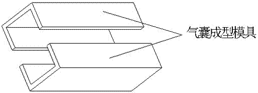
[0024] (1) Process a set of airbag forming molds that match the internal dimensions of the cavity structure. The airbag forming molds are divided into upper and lower parts, and there is a cooperative relationship between them, such as figure 1 ;

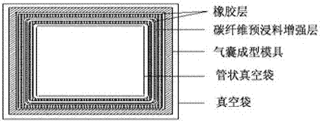
[0025] (2) Use two airbag forming molds respectively to pave the airbag tooling. The airbag tooling uses rubber as the main material, and the rubber is laid layer by layer on the...


PUM


Abstract

The invention discloses a gas channel design method for molding of a composite material cavity-structure gas bag, wherein the method comprises the steps: processing a set of gas bag molding die matched with the cavity internal size of a cavity structural member, laying the inner surface of the gas bag molding die with a gas bag fixture, carrying out hot press molding, laying a cavity pre-compaction die with a member cavity partial pre-immersed material, carrying out vacuum seal on an outer layer with a vacuum bag, and completing pre-pressing; taking down the cavity partial pre-immersed material, placing at a corresponding cavity position of the member molding die, and putting the cured gas bag fixture, finally covering with a web partial pre-immersed material having pre-pressing completed, carrying out vacuum seal on the outer surface of a web with a vacuum bag, allowing to enter a hot press tank, and thus molding the composite material prepared member. The method can be more evenly and accurately transmit the hot press tank applied pressure, avoids the composite material member from generating an ultra-poor thickness phenomenon, abandons a metal gas nozzle, adopts an end opening mode, eliminates the possibility of breakage and gas leakage generated at a joint of the metal nozzle and the gas bag, and greatly prolongs the service life of the gas bag; and with the above two points, the molding quality of the prepared member can be effectively guaranteed, and the production qualified rate and efficiency are increased.

Description

technical field [0001] The invention relates to the technical field of advanced composite material manufacturing, in particular to a gas channel design method for composite material cavity structure air bag forming. Background technique [0002] Resin-based carbon fiber composite materials have superior properties such as specific strength and specific stiffness, strong designability, good fatigue fracture resistance, corrosion resistance, and good dimensional stability. They are currently widely used in aviation, aerospace, transportation and other fields. High-performance structural materials. Among various carbon fiber composite molding processes, the autoclave process has uniform molding temperature and pressure, and has good adaptability to parts of different materials, shapes, sizes and structures. One of the main process methods of material components. [0003] With the increasing requirements for the strength and stiffness of composite parts, the structure of the p...

Claims


Application Information

Patent Timeline
Patent Type & Authority Patents(China)
IPC IPC(8): B29C70/44B29C70/54
CPCB29C70/446B29C70/54
Inventor 黎玉钦贾傲王国平马秀菊刘备备谢海洋黄毅
Owner 航天海鹰(镇江)特种材料有限公司
Why Eureka
Try Eureka