
Electric wire routing structure

A technology for electric wires and protective components, which is applied in the field of wire layout structure of protective components, can solve the problems of increased workload, increased number of parts, and increased transportation efficiency, so as to reduce the workload of assembly, reduce the number of parts, and improve transportation. efficiency effect

Active Publication Date: 2015-04-29
YAZAKI CORP +1
View PDF11 Cites 4 Cited by
  • Summary
  • Abstract
  • Description
  • Claims
  • Application Information

AI Technical Summary

Problems solved by technology

This requires fixing members to be provided at smaller intervals, leading to problems in that the number of parts increases and the workload for assembly increases
However, when both ends of the inner bellows are fixed to electric wires and both ends of the outer bellows are fixed to the inner bellows as in the conventional double-walled bellows, a gap occurs between the inner and outer bellows during bending. Poor shape cannot be absorbed, causing another problem of not sufficiently increasing transport efficiency due to smaller bending curvature

Method used


Image

  • Electric wire routing structure
  • Electric wire routing structure
  • Electric wire routing structure

Examples


Embodiment Construction

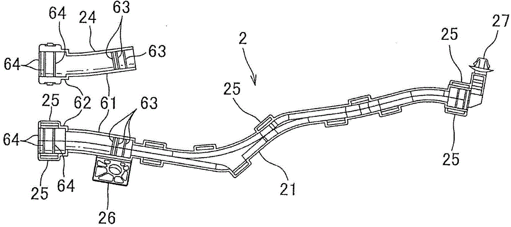
[0042] will now refer to Figure 1A to Figure 5B A wire routing structure according to an embodiment of the present invention will be described. The electric wire routing structure of this embodiment is used as a structure that is used in, for example, a vehicle, particularly an electric vehicle running with the driving force of an electric motor or a vehicle running with both the driving force of the engine and the electric motor. In a hybrid car, it is connected between the battery and the inverter and between the inverter and the electric motor. The electric wire routing structure is configured to have electric wires W connected to electric devices and an outer member 1 serving as a protective portion covering and protecting the electric wires W, wherein the electric wires W covered with the outer member 1 are laid longitudinally, for example, on the underfloor of the vehicle. extend. The electric wire W connects, for example, a battery installed in a trunk room on the re...


PUM


Abstract

Provided is an electric wire routing structure which increases rigidity of mounting to a vehicle, etc., to suppress vibration, and which can increase conveyance efficiency and assembling workability. An exterior member (1) is provided with a stiff first protector (2) provided on one side in the longitudinal direction of a wire (W), a stiff second protector (3) provided on the other side thereof, an inside corrugated tube (4) which covers the outside of the wire (W) across the first protector (2) and the second protector (3), and an outside corrugated tube (5) which covers the outside of the inside corrugated tube (4). One end (41, 51) of the inside corrugated tube (4) and the outside corrugated tube (5) is fixed to the first protector (2); the other end (42) of the inside corrugated tube (4) is fixed to the second protector (3) and the other end (52) of the outside corrugated tube (5) is supported to allow sliding in the longitudinal direction relative to the second protector (3).

Description

technical field [0001] The present invention relates to an electric wire routing structure, and more particularly, to an electric wire routing structure having a protective member for covering and protecting electric wires. Background technique [0002] In vehicles (specifically, electric vehicles and hybrid vehicles), there has conventionally been proposed a wire routing structure that includes wires (ie, wire harnesses) connecting electrical devices and a protective member (ie, wire harness) for covering and protecting the wires (ie, external members such as bellows) (for example, see Patent Documents 1 and 2). [0003] like Figure 6 As shown in , the wire routing structure disclosed in Patent Document 1 is mounted on a hybrid vehicle 100 on the front side of which an engine room is provided with an engine, an inverter, and an electric motor, and on the hybrid vehicle 100 On the rear side of the powered vehicle 100, the floor, the trunk room, and the like are provided wi...

Claims


Application Information

Patent Timeline
IPC IPC(8): H02G3/04B60R16/02F16L57/00
CPCH02G3/06B60R16/0215H02G3/0468H02G3/0487H02G3/0691H02G3/32
Inventor 饭岛彬友尾河涼太丸井崇義加藤桂介
Owner YAZAKI CORP
Learn More