Apparatus for diagnosing a circuit arrangement

A technology for diagnosing circuits and current measuring devices, applied in the directions of measuring devices, measuring electricity, short-circuit testing, etc., can solve the problems of high diagnostic equipment, cost, inability to distinguish reference potential line diagnosis, etc.

Active Publication Date: 2015-04-29
VTESCO TECH GMBH
View PDF4 Cites 12 Cited by
  • Summary
  • Abstract
  • Description
  • Claims
  • Application Information

AI Technical Summary

Problems solved by technology

[0003] In the diagnosis of the application described, there is the problem that a short circuit to reference potential or a line break cannot be distinguished from the line diagnosis by means of the current or voltage measurement present in each load path.
This results in high outlay for the diagnostic equipment

Method used


Image

  • Apparatus for diagnosing a circuit arrangement
  • Apparatus for diagnosing a circuit arrangement
  • Apparatus for diagnosing a circuit arrangement

Examples


Embodiment Construction

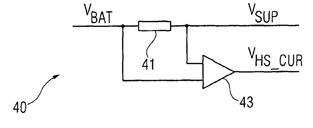
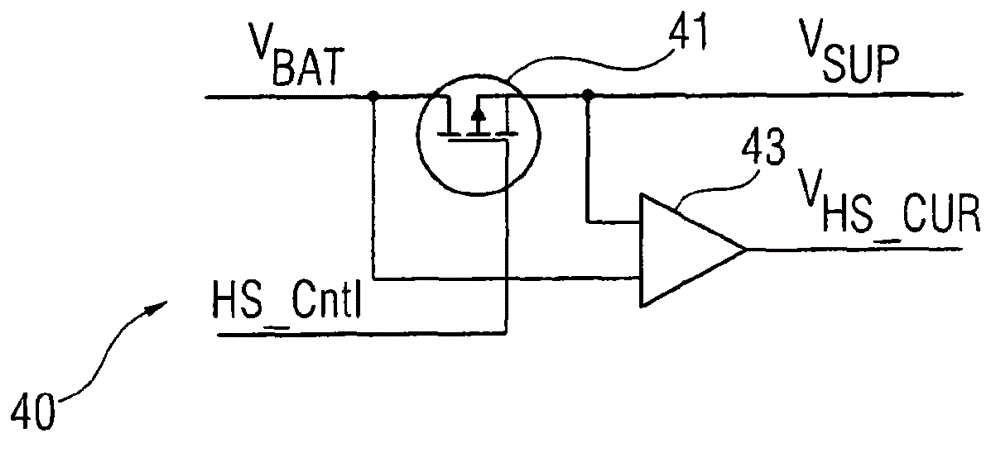
[0029] figure 1 A device according to the invention for diagnosing short circuits and / or wire breaks in a circuit arrangement is represented. In particular, the device is suitable for detecting short circuits to reference potential as well as to supply potential. In particular, the above-mentioned faults can be distinguished here.

[0030] The circuit arrangement to be diagnosed generally includes at least two load circuits connected in parallel. In the present exemplary embodiment, three load circuits 10 , 20 , 30 connected in parallel are shown by way of example. Each load circuit 10 , 20 , 30 is formed by a series connection of a load 11 , 21 , 31 and a controllable switching element 12 , 22 , 32 . The loads 11 , 21 , 31 can be, for example, ignition coils or fuel injection valves of a motor vehicle.

[0031] The load circuits 10 , 20 , 30 are connected between the first supply potential connection 1 and the reference potential connection 3 . The controllable switching...


PUM


Abstract

An apparatus for diagnosing a circuit arrangement for a short circuit and/or a line interruption. The circuit arrangement has at least two load circuits which are connected in parallel. A current measuring device for providing a current signal, which represents the current in the common supply line, is connected in a common supply line to the at least two parallel-connected load circuits. A voltage measuring device detect a node point voltage of each load circuit in the two switching states of the respective switching element. An evaluation device receives the current signal and the node point voltages, converts the current signal into at least one logic current value and the node point voltages into logic voltage values, and infers the type and location of the fault on the basis of prespecified combinations of the at least one logic current value and the logic voltage values.

Description

technical field [0001] The invention relates to a device for diagnosing short circuits and / or wire breaks in a circuit arrangement. The diagnosis includes in particular the detection of short circuits to the reference potential as well as to the supply potential. The circuit arrangement being diagnosed includes at least two load circuits connected in parallel. Background technique [0002] Such diagnostic devices are used, for example, in motor vehicles to check ignition coils or electrification of fuel injection valves. The ignition coil or the fuel injection valve, commonly referred to as the load, is connected to a common power supply in this exemplary application. They are switched on and off via selectable switching elements, usually provided in the control unit, so that the current loop is closed or opened by generating ground. If the switching element is placed between the load and ground, it is called a low-side switching element. [0003] The problem with the di...

Claims


Application Information

Patent Timeline
Patent Type & Authority Applications(China)
IPC IPC(8): G01R31/02G01R31/50
CPCG01R31/54G01R31/52G01R31/50
Inventor H·施毛斯
Owner VTESCO TECH GMBH
Why Eureka
Try Eureka