Eureka AIR delivers breakthrough ideas for toughest innovation challenges, trusted by R&D personnel around the world.

Photovoltaic module support and machining process of photovoltaic module support

A photovoltaic module and processing technology, applied in the support structure of photovoltaic modules, photovoltaic power generation, photovoltaic modules, etc., can solve the problems of high installation cost, high cost of photovoltaic support materials, and long installation period, so as to reduce the pressure , Shorten the installation period and optimize the installation method

Inactive Publication Date: 2015-04-29
BAODING YINGLI DISTRIBUTED ENERGY CO LTD
View PDF9 Cites 2 Cited by
  • Summary
  • Abstract
  • Description
  • Claims
  • Application Information

AI Technical Summary

Problems solved by technology

[0004] Although the above-mentioned installation method can better realize the installation of photovoltaic modules, it also has some disadvantages: first, the manufacture of the cement base needs to wait for the solidification of the cement, and it is also necessary to place the heavy and large number of cement bases One by one hoisting to the roof, electric hammer, electric drill and other tools are needed to install the photovoltaic support, not only the construction process is complicated, but also the installation period is long
Thirdly, the material cost of the photovoltaic bracket composed of C-shaped steel is relatively high, and the long construction period also increases the construction cost, making the installation cost of the entire installation system relatively high

Method used


Image

  • Photovoltaic module support and machining process of photovoltaic module support
  • Photovoltaic module support and machining process of photovoltaic module support
  • Photovoltaic module support and machining process of photovoltaic module support

Examples


Embodiment Construction

[0033] The invention provides a novel photovoltaic module support, which does not need to use a cement base, thereby shortening the installation period, reducing construction difficulty, reducing roof pressure, and reducing installation costs.

[0034] The following will clearly and completely describe the technical solutions in the embodiments of the present invention with reference to the accompanying drawings in the embodiments of the present invention. Obviously, the described embodiments are only some, not all, embodiments of the present invention. Based on the embodiments of the present invention, all other embodiments obtained by persons of ordinary skill in the art without making creative efforts belong to the protection scope of the present invention.

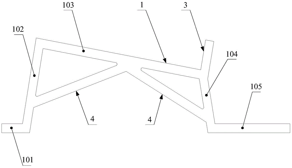
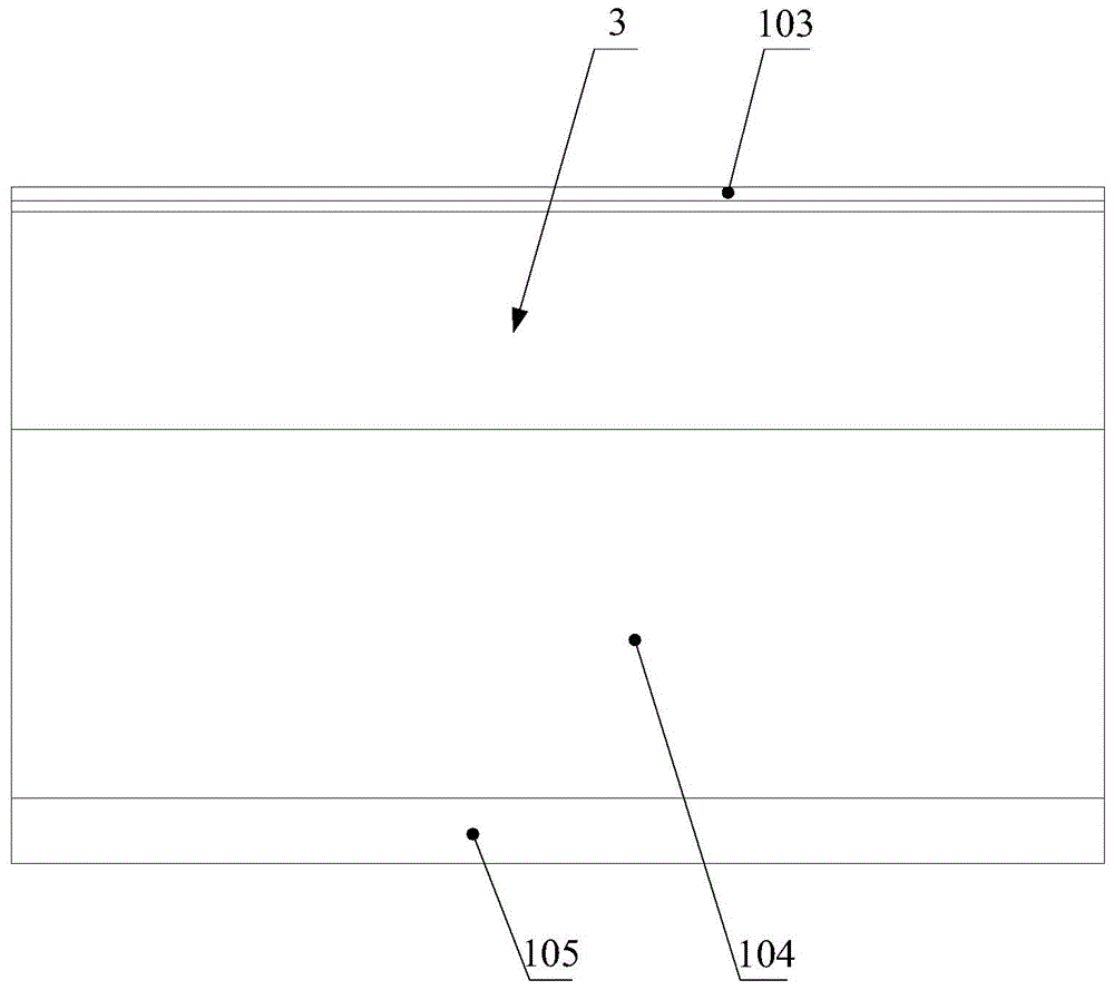
[0035] Such as Figure 1-Figure 7 As shown, the photovoltaic module bracket provided by the embodiment of the present invention refers to a bracket used to support a photovoltaic module 5. In the photovoltaic array, ea...


PUM


Abstract

The invention discloses a photovoltaic module support. The photovoltaic module support comprises a front support and a back support, the front support and the back support can be arranged on a roof, one photovoltaic module is jointly fixed and supported through the front support and the back support, the front support and the back support are each formed by bending a metal plate, and the height of the front support is smaller than the height of the back support so as to achieve inclined supporting of the photovoltaic module. As the front support and the back support are each formed by bending the metal plate, after being produced in batch in a workshop, the front support and the back support can be conveyed to an installation site to be directly installed; in addition, as the front support and the back support can be directly arranged on the roof, and a cement base does not need to be arranged any more, the support of the structure can achieve in-time installation of the photovoltaic module, and the installation period is accordingly shortened; as the cement base is not used, the construction difficulty can be reduced, the pressure borne by a house is reduced, and the installation mode of the photovoltaic module is obviously optimized. The invention further provides a machining process of the photovoltaic module support.

Description

technical field [0001] The present invention relates to the technical field of photovoltaic modules, more specifically, to a photovoltaic module bracket, and the invention also relates to the processing technology of the above-mentioned photovoltaic module bracket. Background technique [0002] Distributed photovoltaic power generation refers to a distributed power generation system that directly converts solar energy into electrical energy by using distributed resources, photovoltaic modules with small installed capacity and arranged near users. Distributed power generation systems are generally built on the user side, mostly on the user's roof, which consists of photovoltaic modules, photovoltaic brackets, DC combiner boxes, grid-connected inverters, AC distribution boxes, cables, etc. Among them, the photovoltaic module converts solar energy into direct current, and the direct current of the photovoltaic array passes through the DC combiner box and then reaches the grid-c...

Claims


Application Information

Patent Timeline
Patent Type & Authority Applications(China)
IPC IPC(8): H02S20/23
CPCH02S20/00Y02B10/10Y02E10/50
Inventor 马圣东何丰廷朱恩来马明崔胜波
Owner BAODING YINGLI DISTRIBUTED ENERGY CO LTD
Why Eureka
Eureka Blog
Learn More