
Spot-weld fatigue life predicting method

A fatigue life prediction and fatigue life technology, applied in special data processing applications, instruments, electrical and digital data processing, etc., can solve the problems of low prediction accuracy, low modeling and calculation efficiency, and achieve the effect of improving efficiency

Inactive Publication Date: 2015-04-29
HUNAN UNIV
View PDF2 Cites 23 Cited by
  • Summary
  • Abstract
  • Description
  • Claims
  • Application Information

AI Technical Summary

Problems solved by technology

[0004] The purpose of the present invention is to solve the problems of low prediction accuracy, low modeling and calculation efficiency, etc. existing in the existing solder joint fatigue prediction method

Method used


Image

  • Spot-weld fatigue life predicting method
  • Spot-weld fatigue life predicting method
  • Spot-weld fatigue life predicting method

Examples


Embodiment Construction

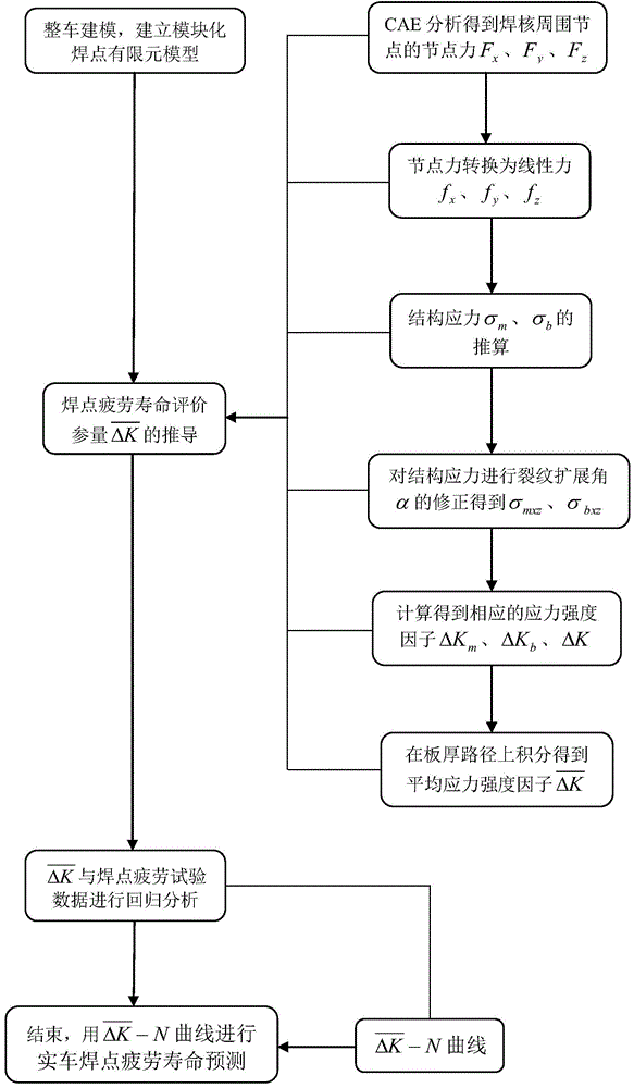
[0042] The following will be combined with Figure 1-9 The technical scheme of the present invention is described in detail

[0043] The invention provides a method for predicting the fatigue life of solder joints, comprising the following steps:

[0044] Step 1. Model the whole vehicle and establish the finite element model of modular solder joints

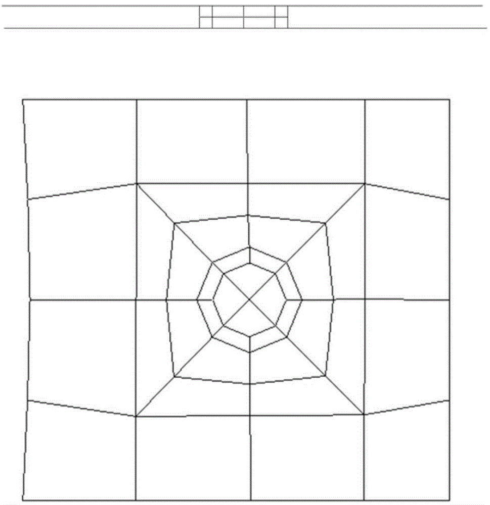
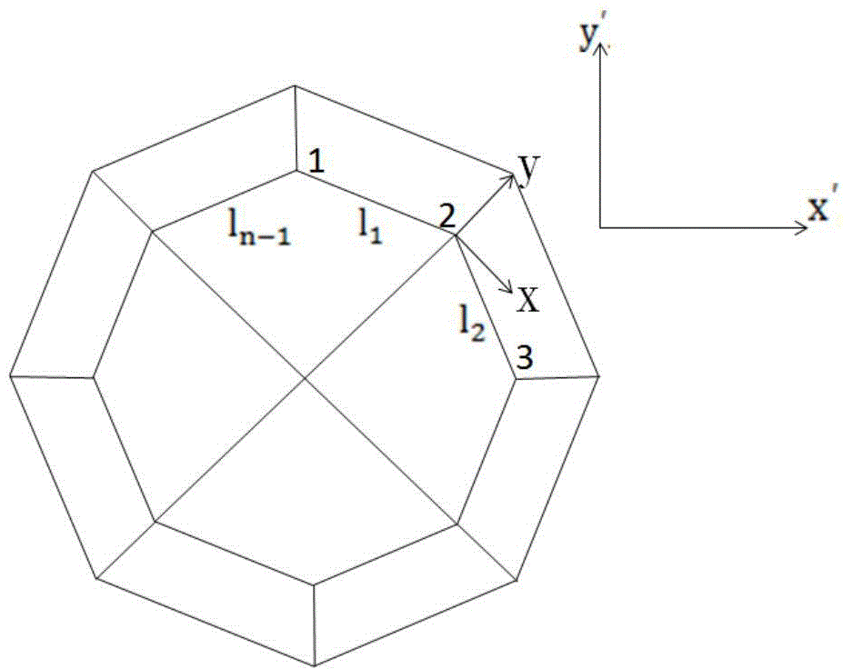
[0045] In vehicle modeling, the established modular solder joint finite element model is as follows: figure 2 As shown, the weld nugget of the solder joint is simulated using two layers of solid elements. In order to solve the problem of matching the finite element model of the solder joint with the structural mesh, each layer is composed of four solid elements to form an equilateral octagon, and the diameter is taken as The actual diameter of the nuclei, the nugget material is assumed to be the same as the parent metal. Then, gradually transition to the basic grid size of 10×10mm through the three-coil shell element.

[004...


PUM


Abstract

The invention relates to a spot-weld fatigue life predicting method. The spot-weld fatigue life predicting method includes steps of 1, modeling a full vehicle and establishing a modularized spot-weld finite element model; 2, deducing spot-weld fatigue life evaluation parameter, mean stress strength factor; 3, subjecting spot-welded joints of different materials to systematic fatigue test, and subjecting the mean stress strength factor and fatigue test data of the spot-welded joints of different materials to regression analysis to obtain a curve of the spot-welded joints of different materials. The spot-weld fatigue life predicting method adopts the modularized spot-weld model to predict the spot-weld fatigue life, in actual application, only nodes of a border unit of the modularized spot-weld model are superposed with nodes of a welding structure unit, and spot-weld modeling efficiency in the full-vehicle modeling is improved.

Description

field of invention [0001] The invention relates to a welding fatigue failure prediction method, in particular to a welding point fatigue life prediction method. Background technique [0002] Resistance spot welding is a traditional welding process in automobile assembly. The connection joints between most parts in automobiles are designed according to the requirements of resistance spot welding, and resistance spot welding is very suitable for lap joints of thin plate structures such as car bodies. According to statistics, about 50% of the fatigue problems of automobile structures are related to solder joints, and about 80% of the fatigue problems of car bodies are related to solder joints. Therefore, it can be said that the fatigue strength of solder joints determines the durability of automobile components. Therefore, using computer-aided analysis in the early stage of design to predict the fatigue life of body solder joints has important practical significance for effecti...

Claims


Application Information

Patent Timeline
IPC IPC(8): G06F19/00
Inventor 宋凯钱涛李光耀成艾国姚威韩越
Owner HUNAN UNIV
Learn More