Device and method for predicting function return address

A return address and return address stack technology, applied in electrical digital data processing, program control design, instruments, etc., can solve problems such as limited function size, and achieve the effect of reducing costs and improving processor performance

Inactive Publication Date: 2015-04-29
C SKY MICROSYST CO LTD
View PDF2 Cites 8 Cited by
  • Summary
  • Abstract
  • Description
  • Claims
  • Application Information

AI Technical Summary

Problems solved by technology

[0004] Studies have shown that, limited by the size of the function, the address offset of the function call is mostly within the range of 1Mb, so it is meaningless to save the high bits of the function return address in the function return address stack in most cases

Method used


Image

  • Device and method for predicting function return address
  • Device and method for predicting function return address
  • Device and method for predicting function return address

Examples


Embodiment 1

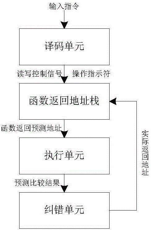
[0033] refer to Figure 1 ~ Figure 4 A function return address prediction device includes a decoding unit, a function return address stack, an execution unit and an error correction unit.

[0034] The instruction decoding unit decodes the input instruction to obtain operation indicator, register index and other information. The operation indicator includes instruction type, operand type, operand number and so on. Instruction types can include arithmetic instructions, memory access instructions, conditional transfer instructions, unconditional transfer instructions, and indirect transfer instructions. Among them, the function call and function return instructions in the indirect transfer instructions must be decoded by the decoding unit. Register index information helps determine function return instructions and provides address information for indirect branch instructions. When the instruction decoding unit decodes the current input instruction as a function call instructio...

Embodiment 2

[0040] refer to Figure 5 , a method for function return address prediction, the method includes the following steps:

[0041] 1) Decode the instruction, decode the function call instruction and the function return instruction, and generate an operation indicator;

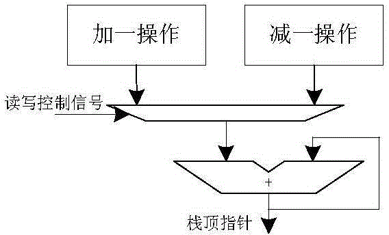
[0042] 2) When the instruction is decoded as a function call instruction, the low M bits of the address of the next instruction are intercepted and stored in the function return address stack; when the instruction is decoded as a function return instruction, the latest entry is popped from the function return address stack The M-bit address of the stack table entry is spliced ​​with the high (N-M) bit address of the function return instruction, encapsulated to generate the predicted address A of the function return instruction, and the table entry index X corresponding to the predicted address A is recorded;

[0043] 3) When the operation indicator indicates a function return instruction, it is judged whether the ...


PUM


Abstract

A device for predicting a function return address comprises an instruction decoding unit, a function return address stack, an execution unit and an error correction unit. The instruction decoding unit is used for decoding an input instruction to generate an operation indicator; the function return address stack comprises S table entries and is used for performing return address prediction on a function return instruction to generate a predicated address A and a corresponding table entry index X; the execution unit is used for receiving the operation indicator of the instruction decoding unit and the predicated address A and the table entry index X of the function return address stack, judging whether the address A is predicated correctly or not when the operation indicator indicates the function return instruction, and generating prediction correctness information and an actual skip address; the error correction unit is used for receiving output of the execution unit, and correcting content directed by the table entry index X in the function return address stack by the actual address B when the function return address is predicated mistakenly. The invention further provides a method for predicting the function return address. By the device and the method, cost of the function return address stack is reduced effectively, and processor performance is improved.

Description

technical field [0001] The invention belongs to the field of microprocessors, in particular to a device and method for function return address prediction. Background technique [0002] The transfer instruction is one of the basic instructions of the processor and widely exists in the program. The transfer instruction will introduce the transfer of program control flow, which is one of the performance killers of the processor. Further, the branch instruction includes conditional branch instruction, unconditional branch instruction and indirect branch instruction. Among them, the function return instruction, as a kind of indirect transfer instruction, is frequently applied to the program return of sub-functions, which has a significant impact on the performance of the processor. In order to speed up the execution speed of function return instructions, middle and high-end embedded processors generally use function return address stacks to provide return address prediction for...

Claims


Application Information

Patent Timeline
IPC IPC(8): G06F9/315
Inventor 王洁范润东刘伯方
Owner C SKY MICROSYST CO LTD
Why Eureka
Try Eureka