
FPGA-based radio frequency signal source circuit

A technology of radio frequency signal source and power circuit, which is applied in instruments, computer control, simulators, etc., can solve the problems of difficulty in realizing circuits such as single sinusoidal signal and loop filter, etc.

Inactive Publication Date: 2015-04-29
TOEC TECH
View PDF5 Cites 5 Cited by
  • Summary
  • Abstract
  • Description
  • Claims
  • Application Information

AI Technical Summary

Problems solved by technology

[0003] At present, the RF signal source circuit is mostly implemented by analog, adopting superheterodyne circuit design, and controlling the VCO voltage-controlled oscillator to generate the required signal frequency through the PLL phase-locked loop. This method can only generate a single sinusoidal signal and a simple analog The modulation method is greatly affected by the environment such as temperature. It is difficult to implement circuits such as loop filters to output signals with a wide frequency range.

Method used


Image

  • FPGA-based radio frequency signal source circuit
  • FPGA-based radio frequency signal source circuit
  • FPGA-based radio frequency signal source circuit

Examples


Embodiment Construction

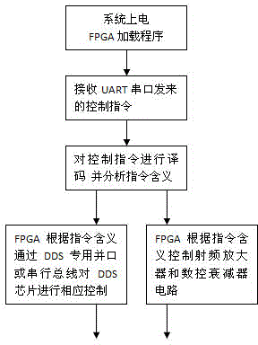
[0010] The present invention will be further described below in conjunction with accompanying drawing:

[0011] refer to figure 1 An FPGA-based radio frequency signal source circuit includes a power supply circuit, an FPGA chip and a working program, a DDS chip circuit, a constant temperature crystal oscillator circuit, a low-pass filter circuit, a radio frequency amplifier and a digitally controlled attenuator circuit, a clock circuit, and an off-chip program storage circuit, JTAG program download debugging circuit and UART serial port circuit; described FPGA chip is respectively connected with power supply circuit, DDS chip circuit, radio frequency amplifier and numerical control attenuator circuit, clock circuit, off-chip program storage circuit, JTAG program download debugging circuit and UART The serial port circuit is connected, the DDS chip circuit is connected with the constant temperature crystal oscillator circuit and the low-pass filter circuit, the low-pass filter ...


PUM


Abstract

The invention discloses an FPGA-based radio frequency signal source circuit. The FPGA-based radio frequency signal source circuit comprises a power supply circuit, an FPGA chip, a working program of the FPGA chip, a DDS chip circuit, a constant-temperature crystal oscillation circuit, a low-pass filter circuit, a radio frequency amplifier, a numerical control attenuator circuit, a clock circuit, an off-chip program storage circuit, a JTAG program unloading and debugging circuit, and an UART serial port circuit. The FPGA-based radio frequency signal source circuit has the characteristics that a single chip integrated DDS chip technology is adopted; the DDS chip is subjected to high-speed control by using the FPGA chip; the work clock of the DDS chip can reach 1 GHz, and the output sinusoidal frequency of the DDS chip can reach 400 MHz; the circuit has a radio frequency output signal power software control function; a radio frequency signal generator circuit can be controlled by external equipment through the UART serial port circuit; the accuracy of a radio frequency output signal is improved by adopting the constant-temperature crystal oscillation circuit; the frequency accuracy is 0.23 Hz; a 14-bit DAC is arranged in the DDS chip.

Description

technical field [0001] The invention relates to a wireless communication system, in particular to an FPGA-based radio frequency signal source circuit. Background technique [0002] In the fields of modern radar, communication and electronic countermeasures, signal generators are widely used, and the requirements for signal indicators are getting higher and higher. Among various types of signal frequency synthesis at present, direct digital frequency synthesis (DDS) technology is a frequency synthesis method developed rapidly in recent years. DDS adopts digital storage technology to realize waveform generation through phase accumulation, amplitude look-up table and digital-to-analog conversion. It has ultra-wide relative bandwidth, ultra-high frequency agility speed, ultra-fine frequency resolution, continuous phase, and full digitalization. , It is widely used due to its superior performance such as easy monolithic integration. [0003] At present, the RF signal source cir...

Claims


Application Information

Patent Timeline
IPC IPC(8): G05B19/042
CPCG05B19/042G05B2219/20
Inventor 常涛张宇苗尧飞宋光伟孙光莫晓婷
Owner TOEC TECH
Learn More