
Optical adjustment structure

A technology of optical adjustment and adjustment parts, which is applied in the field of mechanical components, can solve problems such as complex optical adjustment structures, and achieve the effect of simple adjustment methods and effective structures

Inactive Publication Date: 2015-04-29
张家港恩达通讯科技有限公司
View PDF5 Cites 7 Cited by
  • Summary
  • Abstract
  • Description
  • Claims
  • Application Information

AI Technical Summary

Problems solved by technology

[0005] For this reason, the technical problem to be solved by the present invention is that the structure of the optical adjustment structure is complicated, so as to provide an optical adjustment structure with simple structure and convenient adjustment.

Method used


Image

  • Optical adjustment structure
  • Optical adjustment structure
  • Optical adjustment structure

Examples


Embodiment Construction

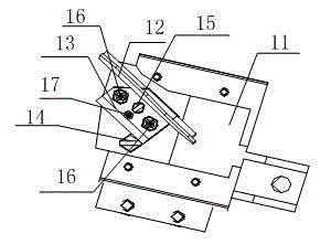
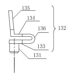
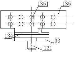
[0030] This embodiment provides an optical adjustment structure, such as Figure 1 to Figure 6 As shown, it includes a fixed frame 13 for installing the reflector 12. The fixed frame 13 is horizontally rotatably mounted on the base 11, and also includes a first adjusting member 14 for driving the fixed frame 13 to rotate horizontally on the base 11. An adjustment member 14 can rotate horizontally on the base 11 around the rotation axis, the outer surface of the first adjustment member 14 is arranged in contact with the side wall of the fixed frame 13, and along the horizontal rotation direction, the outer surface of the first adjustment member 14 is relative to the rotation axis The distance has a linear relationship.

[0031]The above technical solution is the core technical solution of the present invention, the fixed mount 13 is installed on the base 11 and can rotate horizontally on the base 11, the reflector 12 is installed on the fixed mount 13, and the rotation of the f...


PUM


Abstract

The invention relates to an optical adjustment structure. The optical adjustment structure comprises a fixed bracket used for mounting a reflector and mounted on a base in a horizontally rotatable manner, and further comprises a first adjusting piece used for driving the fixed bracket to rotate horizontally on the base, wherein the first adjusting piece can rotate horizontally on the base around a rotating shaft; the outer side surface of the first adjusting piece is in contact with the side wall of the fixed bracket; in the horizontal rotating direction, the outer side surface of the first adjusting piece relative to the rotating shaft is in linear relation; when the first adjusting piece rotates in the horizontal direction, the outer side surface of the first adjusting piece drives the side wall of the fixed bracket to rotate on the base, and the reflector rotates together, so that rotation of the reflector on the base in the horizontal direction is realized. According to the optical adjustment structure, the reflector can be driven to rotate horizontally on the base as long as the first adjusting piece is rotated, so that the adjustment mode is simple, convenient and effective.

Description

technical field [0001] The invention relates to mechanical parts of an optical system, in particular to an optical adjustment structure. Background technique [0002] With the demand for miniaturization and light weight of optical products, usually designed optical products such as projectors have a relatively compact structure; moreover, because optical products themselves have high requirements for precision, that is, a small position or size error of a certain device is It may cause the optical system to fail to meet the design requirements. Therefore, fine-tuning and fine-tuning of optical products is a common means to meet the design requirements in the assembly and debugging process. Moreover, designing a structure that is convenient for light adjustment is a sufficient condition to ensure the output and quality of optical products. . Reasonable optical adjustment structure design also helps to reduce the processing accuracy of individual parts in optical products, wh...

Claims


Application Information

Patent Timeline
IPC IPC(8): G02B7/182G03B21/28
CPCG02B7/1821G03B21/28
Inventor 张华辉
Owner 张家港恩达通讯科技有限公司
Learn More