A Method for Realizing Field Calibration of Synchronous Transmitter/Resolver
A technology of synchronous transmission and on-site calibration, which is applied in the direction of instruments, measuring devices, and measuring electrical variables, etc. It can solve the problems of high calibration environment and standard requirements, unfulfilled calibration requirements, and low calibration accuracy, so as to achieve stable and reliable calibration process , easy implementation and wide adaptability
- Summary
- Abstract
- Description
- Claims
- Application Information
AI Technical Summary
Problems solved by technology
Method used
Image
Examples
Embodiment 1
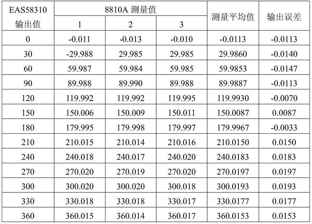
[0030] The steps of the calibration method involved in the present invention are:
[0031] Step 1: Selection of Calibration Equipment
[0032] Step 1.1: Select the master standard for calibration
[0033] The model of the angular position indicator is 8810A: the technical parameters are: angle measurement range: 0~360°; resolution: 0.0001°; measurement allowable error: ±0.004°.
[0034] Step 1.2: Supporting Equipment
[0035] The parameters for selecting the onboard power supply are power supply frequency: 400Hz, power supply voltage: 115V or 26V variable.
[0036] Step 2: Calibration Preparation
[0037] Step 2.1: Power on and warm up
[0038] As the standard angular position indicator and the large equipment where the calibrated synchronous transmitter / resolver is located, it is normally connected to 220V, 50Hz mains power. Warm up for 15 minutes after starting up.
[0039] Step 2.2: Reference Signal Input
[0040] After power on, according to the use requirements of ...
Embodiment 2
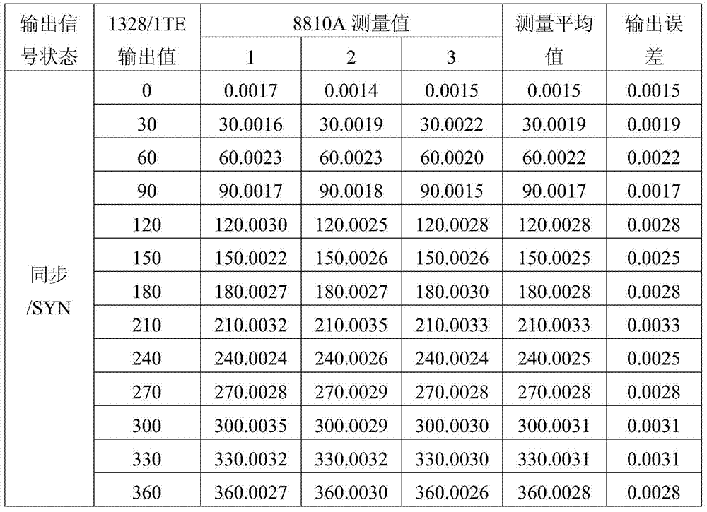
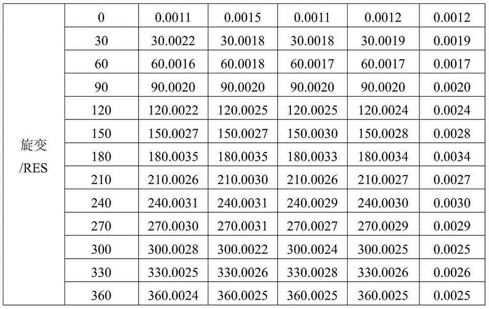
[0052] Step 1: Selection of Calibration Equipment
[0053] Step 1.1: Select the master standard for calibration
[0054] The model of the angular position indicator is 8810A: the technical parameters are: angle measurement range: 0~360°; resolution: 0.0001°; measurement allowable error: ±0.004°.
[0055] Step 1.2: Supporting Equipment
[0056] The parameters for selecting the onboard power supply are power supply frequency: 400Hz, power supply voltage: 115V or 26V variable.
[0057] Step 2: Calibration Preparation
[0058] Step 2.1: Power on and warm up
[0059] As the standard angular position indicator and the large equipment where the calibrated synchronous transmitter / resolver is located, it is normally connected to 220V, 50Hz mains power. Warm up for 15 minutes after starting up.
[0060] Step 2.2: Reference Signal Input
[0061] After power on, according to the use requirements of the calibrated synchronous transmitter 1328 / 1TE, use the special power supply system at...
PUM
 Abstract
Description
Claims
Application Information
 - R&D
- Intellectual Property
- Life Sciences
- Materials
- Tech Scout
- Unparalleled Data Quality
- Higher Quality Content
- 60% Fewer Hallucinations
Browse by: Latest US Patents, China's latest patents, Technical Efficacy Thesaurus, Application Domain, Technology Topic, Popular Technical Reports.
© 2025 PatSnap. All rights reserved.Legal|Privacy policy|Modern Slavery Act Transparency Statement|Sitemap|About US| Contact US: help@patsnap.com


