
Throttle Control Method of Centrifugal Chiller

A water chiller, throttling control technology, applied in refrigerators, refrigeration components, refrigeration and liquefaction, etc., can solve the problems of unstable operation of the unit, fluctuation of liquid level display value, low exhaust superheat, etc., to save liquid position sensor or temperature sensor, improving reliability and reducing cost

Active Publication Date: 2017-01-04
GREE ELECTRIC APPLIANCES INC +1
View PDF5 Cites 0 Cited by
  • Summary
  • Abstract
  • Description
  • Claims
  • Application Information

AI Technical Summary

Problems solved by technology

[0003] 1. Take the liquid level of the evaporator as the control target: when the unit is actually running, the shell tube is in a boiling state, and there is a large deviation in the judgment of the real-time liquid level by the liquid level sensor, resulting in large fluctuations in the liquid level display value, so the section The flow electronic expansion valve increases and decreases in a wide range, resulting in extremely unstable operation of the unit
[0004] 2. Take the exhaust superheat as the control target: Due to the system characteristics of the centrifugal chiller, the exhaust superheat is low (no obvious water-cooled screw, etc.), resulting in the exhaust temperature when the throttling electronic expansion valve is adjusted in a wide range There is no obvious change, that is, it brings a blind area of ​​control

Method used


Image

  • Throttle Control Method of Centrifugal Chiller
  • Throttle Control Method of Centrifugal Chiller
  • Throttle Control Method of Centrifugal Chiller

Examples


Embodiment Construction

[0017] The present invention will be described in detail below with reference to the accompanying drawings and examples.

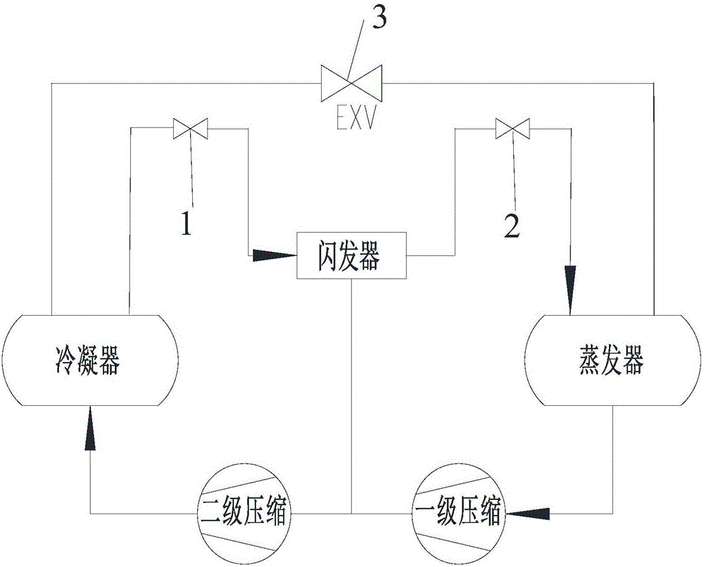
[0018] Such as figure 1 As shown, the main throttling circuit of the centrifugal chiller is the throttling of the primary orifice plate 1 and the secondary orifice plate 2, and the auxiliary throttling circuit is the throttling electronic expansion valve 3.

[0019] In the throttling control design, the calculation of throttling components (first-stage orifice plate 1, second-stage orifice plate 2 and electronic expansion valve 3) is generally based on the nominal full load, while the first-stage orifice plate 1 and the second-stage orifice There is no significant change in the flow rate of refrigerant circulating through plate 2 under partial load, so the throttling electronic expansion valve 3 on the auxiliary throttling circuit from the condenser to the evaporator is very important to adjust under partial load.

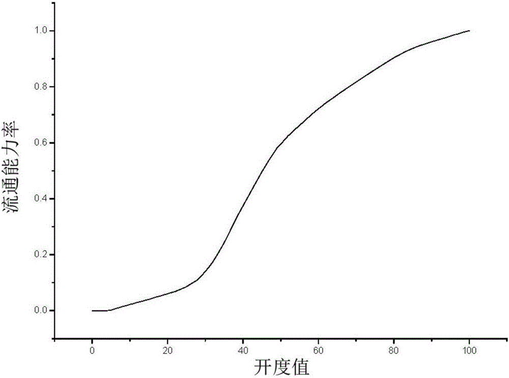
[0020] combine image 3 As shown, the ...


PUM


Abstract

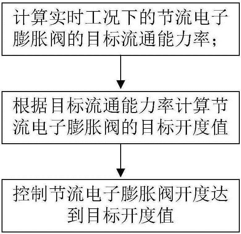
The invention provides a throttling control method of a centrifugal type water chiller, which is used for controlling a throttling electronic expansion valve of an auxiliary throttling loop of the centrifugal type water chiller. The throttling control method comprises the following steps of S1, calculating the target flow capacity rate of the throttling electronic expansion valve under the real-time working condition; S2, according to the target flow capacity rate, calculating the target opening degree value of the throttling electronic expansion valve; S3, controlling the opening degree of the throttling electronic expansion valve to reach the target opening degree value. The throttling control method has the advantages that the opening degree value of the throttling electronic expansion valve is directly used as a control target, so more accuracy, stability and reliability are realized, and the drifting risk in the signal transfer process is effectively reduced; in addition, compared with the existing liquid level control and air exhaust overheat control methods, the arrangement of a liquid level sensor or a temperature sensor is not needed, the cost is reduced, and the reliability is improved.

Description

technical field [0001] The invention relates to the control field of a centrifugal chiller, in particular to a throttling control method for a centrifugal chiller. Background technique [0002] Centrifugal chillers are known for their large cooling capacity and high energy efficiency. Under partial load, the adjustment and throttling scheme of the system flow is very important. In the current throttling technology, most of them adopt the throttling scheme of the main and auxiliary, that is, the parallel throttling of the orifice plate and the regulation of the electronic expansion valve. The flow rate of the orifice plate is given, so the control technology of the throttling electronic expansion valve is the key. The control technology currently used mostly adopts the liquid level or exhaust superheat as the control target, and the target value under the ideal state is given to automatically adjust the opening of the throttling electronic expansion valve to the target value...

Claims


Application Information

Patent Timeline
Patent Type & Authority Patents(China)
IPC IPC(8): F25B49/00
CPCF25B49/00
Inventor 周宇赵忠民潘翠周庭宇韩飞刘贤权王娟周堂李剑金成召
Owner GREE ELECTRIC APPLIANCES INC
Learn More