
Pressure-stabilizing valve

A pressure-stabilizing valve and valve hole technology, applied in the field of pressure-stabilizing valves, can solve problems such as flow drop, low flow, insufficient toilet flushing, etc., and achieve the effect of protecting components

Inactive Publication Date: 2015-04-29
GLOBE UNION INDAL
View PDF9 Cites 10 Cited by
  • Summary
  • Abstract
  • Description
  • Claims
  • Application Information

AI Technical Summary

Problems solved by technology

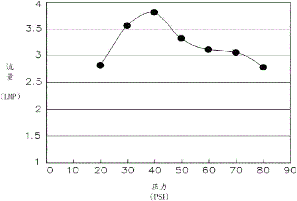
[0003] After using the above-mentioned patented product for experiments, it was found that its performance in stabilizing flow and pressure is not ideal, especially when the water source is under high pressure, its flow rate appears to be low, compared with its own maximum flow rate, it drops by more than 20%, such as figure 1 As shown, it is the pressure and flow curve of the actual test of the patented decompression regulator and current stabilizer. It can be clearly seen that when the water source pressure is at 40PSI, its flow rate reaches a maximum of about 3.8LPM, and when the water source is at 20PSI Under the condition of low water pressure, it is easy to imagine that the flow rate will naturally decrease, as shown in the figure, it will drop to about 2.8LPM, but when the water source is in the state of high water pressure of 80PSI, the flow rate will also drop to about 2.8LPM , the maximum drop has reached about 26%. Therefore, it is conceivable that when the water source pressure is in a high water pressure state, the low flow phenomenon of the product of the pressure reducing and stabilizing flow stabilizer will lead to an obvious shortage of flushing water in the toilet, and then Affect the sewage discharge performance and stability
[0004] After analyzing the pressure-reducing, stabilizing and current-stabilizing device of the above-mentioned patent case, it is found that the water source has a defect of low flow when the water source is under high pressure. Furthermore, the flow rate of its stabilizer products is determined by the opening of the sealing ring and the end face of the inner cavity valve seat, and the opening determines the size of the water cross-sectional area that allows water to pass through between the two. However, we It is found that in its structural design, when the pressure of the water source gradually increases and the opening between the two approaches the minimum value, the cross-sectional area of ​​the water will be reduced sharply instead of gradually reduced. Changes in the reduction of ground will cause the flow rate of the product through the stabilizer to drop rapidly, and then the above-mentioned obvious defects appear
In addition, it is also found that when the water flow passes through the sealing ring and the end face of the valve seat in the inner cavity of the housing, especially when the valve core is relatively displaced due to high pressure to provide a decompression effect, the flow of the water flow is obviously hindered and not smooth enough. Indirectly cause the effect of voltage stabilization and current stabilization to be significantly affected

Method used


Image

  • Pressure-stabilizing valve
  • Pressure-stabilizing valve
  • Pressure-stabilizing valve

Examples


Embodiment Construction

[0033] The technical solutions of the present invention will be further described below in conjunction with the accompanying drawings and specific embodiments. It should be understood that the specific embodiments described here are only used to explain the present invention, not to limit the present invention.

[0034] The invention provides a pressure stabilizing valve.

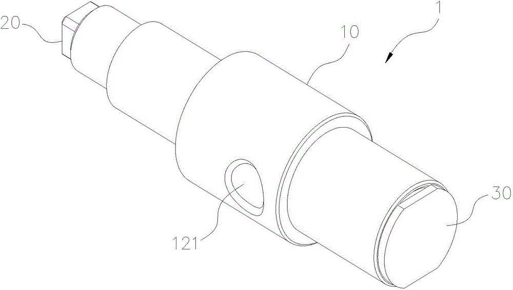
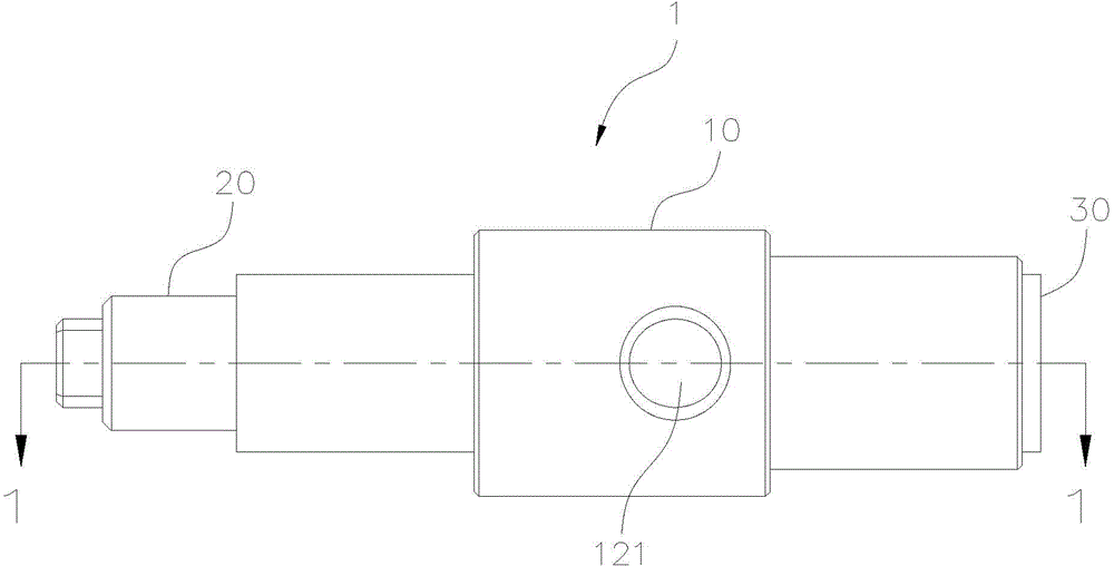
[0035] Such as Figures 2 to 5 As shown, the present invention provides a preferred embodiment of a pressure stabilizing valve. The stabilizing valve 1 includes a housing 10, a left end cover 20, a right end cover 30 and a valve core assembly 40; .

[0036] The housing 10 has a left chamber 11, a right chamber 12, a valve hole 13 between the left and lower chambers 11 and 12, a left opening 14 on the left end side, and a valve hole 14 on the right end side. 15 of the right opening. A water inlet 121 is arranged on the surrounding wall of the lower chamber 12; a water outlet 131 is arranged on the surrou...


PUM


Abstract

The invention provides a pressure-stabilizing valve comprising a shell, a left end cover, a right end cover and a spool component. The shell comprises a left chamber, a right chamber and a valve hole provided between the left and right chambers; the peripheral wall of the right chamber is provided with a water inlet; the peripheral wall of the valve hole is provided with a water outlet; a junction of the right chamber and the valve hole is provided with a valve seat portion having an inner conical wall; the left end cover and the right end cover are hermetically connected to two ends of the shell, respectively; the spool component penetrates the valve hole of the shell and comprises a piston portion and a sealing portion; the piston portion is limited in the left chamber of the shell and hermetically slides in the axial direction; the sealing portion can be hermetically abutted to the inner conical wall. Through relieved changes in area of water passing between the sealing portion and the inner conical wall along with gradual increase of water pressure, the water from the water inlet to the water outlet is well pressure-relieved, pressure-stabilized and flow-stabilized, especially when a water resource is under the high pressure 50 PSI (pounds per square inch) to 100 PSI.

Description

technical field [0001] The invention relates to the field of a valve component used in a toilet flushing system, in particular to a pressure stabilizing valve. Background technique [0002] The pressure stabilizing valve is a device commonly used in the toilet flushing system. Its main purpose is to properly decompress, stabilize the pressure and stabilize the flow. Especially when the water source is under high pressure, it can also maintain stable water pressure and flow, and at the same time avoid instantaneous Extremely high explosive pressure can be generated, causing damage to the product. Patent CN102678994A discloses a new type of automatic decompression and voltage stabilization regulator, which is suitable for toilet flushing systems without a water tank. [0003] After using the above-mentioned patented product for experiments, it was found that its performance in stabilizing flow and pressure is not ideal, especially when the water source is under high pressure,...

Claims


Application Information

Patent Timeline
Patent Type & Authority Applications(China)
IPC IPC(8): F16K17/04
CPCF16K1/38F16K17/30F16K27/0254F16K31/1221
Inventor 郭仲裕吴明佳
Owner GLOBE UNION INDAL
Learn More