
ventilated panoramic roof

A ventilated and panoramic technology, applied in the roof field of buildings, can solve problems such as poor room lighting, achieve the effects of reducing energy consumption, facilitating mass production, and solving lighting and ventilation problems

Inactive Publication Date: 2018-01-19
BEIJING UNIV OF CIVIL ENG & ARCHITECTURE
View PDF7 Cites 0 Cited by
  • Summary
  • Abstract
  • Description
  • Claims
  • Application Information

AI Technical Summary

Problems solved by technology

[0003] The present invention provides a ventilated panoramic roof in order to avoid the disadvantages of the above-mentioned prior art, so as to solve the problem of daylighting in poorly located rooms

Method used


Image

  • ventilated panoramic roof
  • ventilated panoramic roof
  • ventilated panoramic roof

Examples


Embodiment Construction

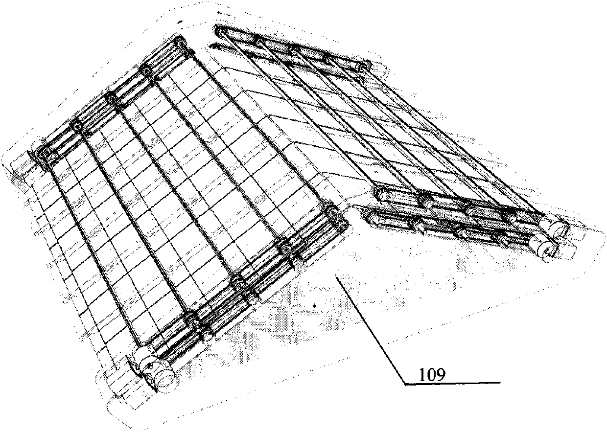
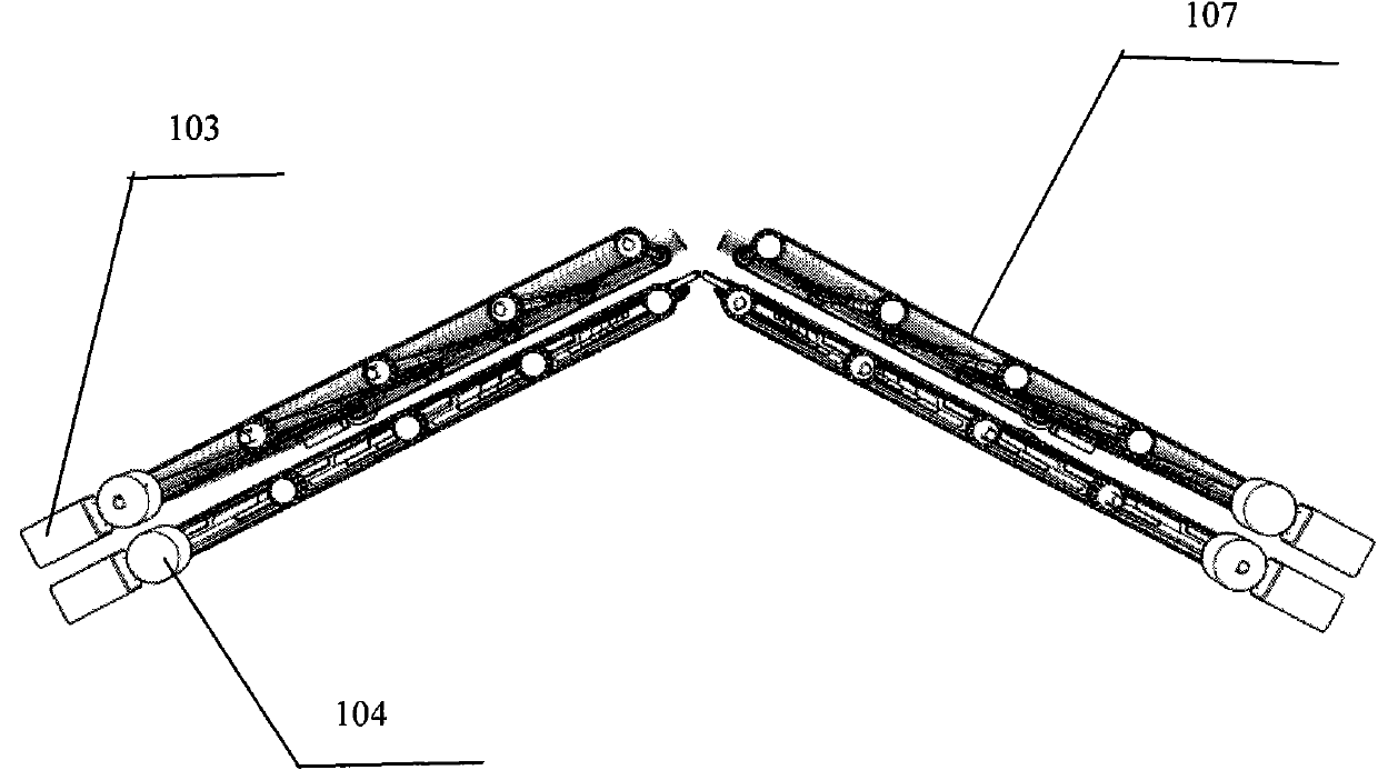
[0025] see Figure 1 to Figure 7 , a ventilated panoramic roof, which includes a driving part and a tile part; wherein, the tile part includes a transparent layer made of transparent tiles 101 and an opaque layer made of opaque tiles 102, and the transparent tiles 101 and opaque The tiles 102 are all provided with through holes passing through the transparent tile 101 and the opaque tile 102;

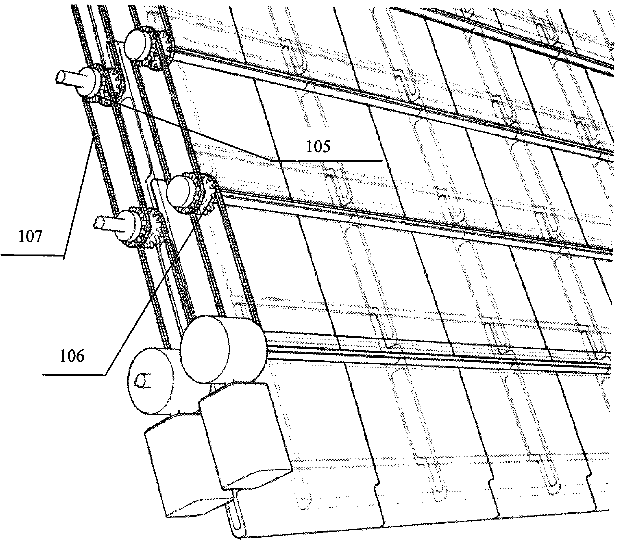
[0026] The drive part includes a drive motor 103, a gearbox 104, and a main shaft 105 that passes through the through holes of the transparent tile 101 and the opaque tile 102 and can drive the tiles to rotate; two ends of each main shaft 105 are respectively arranged. The toothed discs 106, the toothed discs 106 between different main shafts 105 are connected by a chain 107 and carry out power transmission; each gear is equipped with a ratchet 108 for fixing the rotation angle of the main shaft 105; Sleeved on the main shaft 105 and can be driven to rotate by the main shaft 105; the i...


PUM


Abstract

The invention discloses a ventilated panoramic roof, which has the functions of ventilation and lighting, and can arbitrarily adjust the amount of ventilation and the amount of light entering according to different requirements. The present invention comprises two parts of a tile part and a driving part. The tile part includes two kinds of tiles, the upper layer is a transparent material tile, and the lower layer is an opaque tile. Each row of tiles is laid on the roof through a main shaft; each layer of tiles is equipped with a motor, and the motor is connected to the gearbox. On the row of main shafts at the bottom of each layer of tiles; two toothed discs are installed at both ends of each main shaft, which are connected with two adjacent main shafts through chains, so as to realize power transmission. The ventilated panoramic roof of the present invention has the advantages that the user can freely adjust the amount of ventilation and the amount of incoming light according to requirements.

Description

technical field [0001] The invention relates to a roof of a building, in particular to a ventilated panorama roof for a house with bad lighting adjustment. Background technique [0002] The side rooms of buildings such as courtyard houses have poor orientation and usually do not have large windows, so the lighting conditions are not satisfactory. When the lights are not turned on during the day, the light in the house is dim, which is not conducive to the health of human eyes. Long-term use of electric lighting is not only a waste of resources, but also harmful to health. Due to the orientation of the house, increasing the window area alone is not enough to solve the lighting problem, so other methods are needed to solve the lighting problem, and the roof adjustment is undoubtedly the best choice. In addition, with the development of science and technology and the improvement of human living standards, people rely more and more on home appliances such as air conditioners fo...

Claims


Application Information

Patent Timeline
Patent Type & Authority Patents(China)
IPC IPC(8): E04B7/16E04D1/20
Inventor 秦建军许世卿袁齐刘永峰鲁增辉武伯有
Owner BEIJING UNIV OF CIVIL ENG & ARCHITECTURE
Learn More