A wire rope brake

A technology of brakes and wire ropes, which is applied in the field of elevator safety brakes and automatic reset wire rope brakes. It can solve the problems of long control delay, limited operating space, and high reset, so as to reduce delay and improve reliability. Effect

Active Publication Date: 2017-02-01
HANGZHOU HUNING ELEVATOR PARTS CO LTD
View PDF1 Cites 1 Cited by
  • Summary
  • Abstract
  • Description
  • Claims
  • Application Information

AI Technical Summary

Problems solved by technology

[0003] After searching the existing technical literature, it is found that the current wire rope brake is designed based on the uplink overspeed protection, and the mechanical manual reset method is the main method, which brings a lot of problems to the limited operating space, high floors and machine room-less elevators. great inconvenience
In addition, when the power is triggered, an intermediate control mechanism is added, the control delay is long, the current of the electromagnet is relatively large, the backup power capacity is large, and the power consumption is high.
Therefore, its control principle, braking force and brake lining life are not suitable for car accidental movement protection

Method used


Image

  • A wire rope brake
  • A wire rope brake
  • A wire rope brake

Examples


Embodiment Construction

[0039] Below in conjunction with accompanying drawing, preferred embodiment of the present invention is described in detail

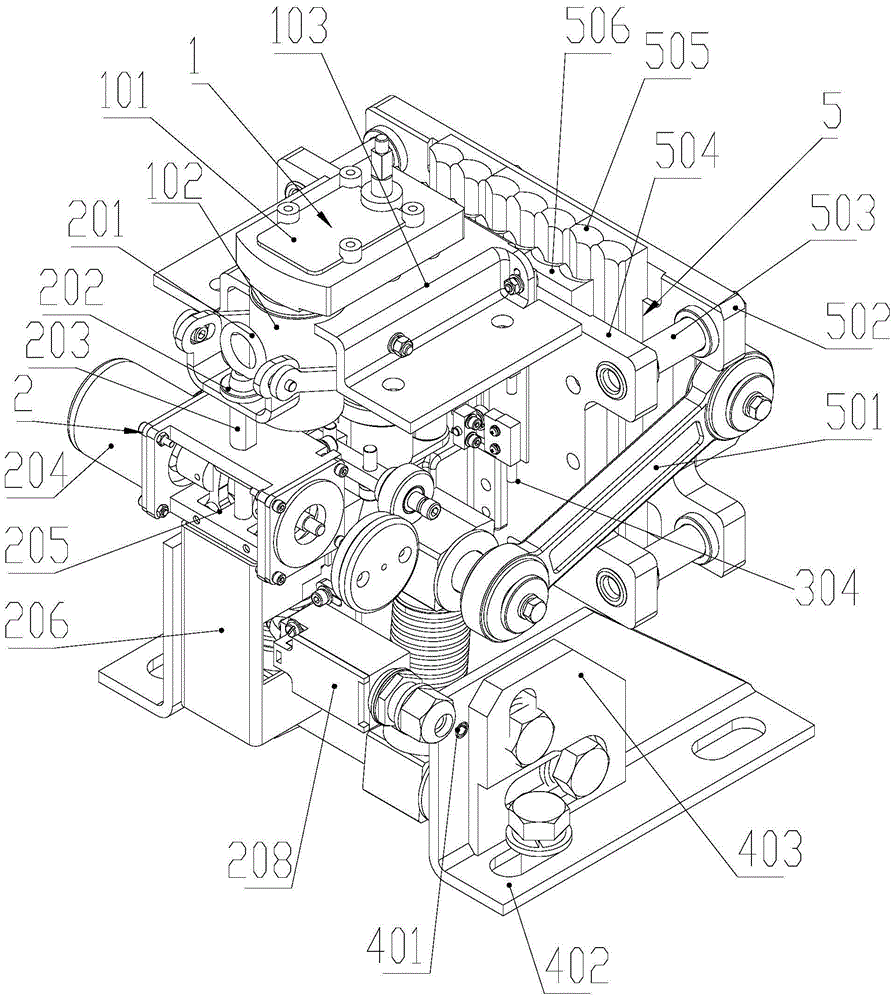
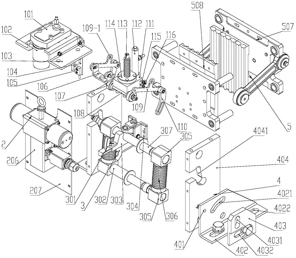
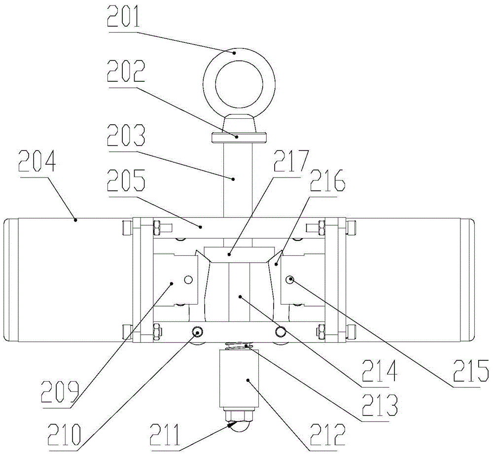
[0040] see Figure 1-4The wire rope brake in this embodiment includes an energy storage locking mechanism, a friction dynamic / fixed brake lining mechanism, a bracket mechanism, an impact trigger mechanism, and a motor screw reset mechanism. The energy storage locking mechanism and the brake lining mechanism are installed on the bracket mechanism. The impact trigger mechanism is installed on the rear side plate, and the reset mechanism is installed on the top plate. The specific structure is as follows:

[0041] The top plate 103 is installed on the upper part of the wire rope brake, the left and right side plates 404 are respectively installed on the support 402 on both sides of the wire rope brake, the support 402 is fixedly installed on the beam through the bottom mounting hole, and the rear side plate 207 is installed on the left and right sides of t...


PUM


Abstract

The invention discloses a steel wire rope brake. A movable brake plate is matched with a connecting arm in a rotating manner, wherein the other end of the connecting arm is matched with a sliding shaft in the rotating manner; the two ends of the sliding shaft are arranged in the cam surfaces of two side plates respectively; a fixed brake plate is provided with a locking hook frame which is provided with a locking hook capable of locking the sliding shaft; electromagnets are arranged on the two sides of an electromagnet seat respectively; a guide pillar is fixedly connected to the upper end of an impact rod after movably penetrating through the electromagnet seat; the impact rod movably penetrates through the electromagnet seat; the lower section of the impact rod is sleeved with a spring; the lower end of the impact rod is opposite to the swinging end of the locking hook; a pressure block is arranged on the impact rod, and is positioned in the electromagnet seat; inclined surfaces are formed on the two sides of the pressure block; two support rods are arranged in the electromagnet seat, and form upwards inclined surfaces; the lower ends of the support rods are arranged on the electromagnet seat in the rotating manner; the support rods can be pressed by the electromagnets; the sliding shaft is provided with an upper spring seat; a spring support shaft is arranged between the two side plates, and is provided with a lower spring seat; an energy storage part is arranged between the upper and lower spring seats; an impact triggering mechanism can be reset by a resetting mechanism.

Description

technical field [0001] The invention belongs to the technical field of mechanical manufacturing, and relates to an elevator safety braking device, in particular to an automatic reset wire rope brake. Background technique [0002] Existing steel wire rope brakes for elevators are mainly protection devices for upward overspeeding of elevators. They adopt the mode of power-on trigger action and manual mechanical reset in case of failure. Relevant requirements of standards for car accidental movement protection devices. Secondly, in terms of the reset method, the reset by manual operation cannot meet the normal use needs of customers. Again, its friction brake lining friction coefficient is little, wears and teares fast, and life-span is short, also can't satisfy the braking life requirement of car accidental movement simultaneously. For this reason, it is necessary to improve the design of the existing wire rope brake to make it more in line with the standard, with more perfe...

Claims


Application Information

Patent Timeline
Patent Type & Authority Patents(China)
IPC IPC(8): B66D5/02B66B5/02
CPCB66B5/04B66B5/185B66B5/24
Inventor 邹家春姚荣康卢灵明何新杨东
Owner HANGZHOU HUNING ELEVATOR PARTS CO LTD
Why Eureka
Try Eureka