
Flat nozzle

A technology of flat nozzles and backing plates, which is applied in the direction of spraying devices, spraying devices, etc., can solve the problems of shortening the life of the nozzles, being easily blocked by debris, and affecting the use of the nozzles, so as to increase the flow rate and not be easily blocked. The effect of increasing the service life

Inactive Publication Date: 2015-04-29
范永禧
View PDF0 Cites 0 Cited by
  • Summary
  • Abstract
  • Description
  • Claims
  • Application Information

AI Technical Summary

Problems solved by technology

[0004] The purpose of the present invention is to provide a flat nozzle, which aims to solve the problem that the water outlet of the existing common spiral nozzle is too small, and it is easy to be blocked by debris, which affects the use effect of the nozzle and even shortens the life of the nozzle.

Method used


Image

  • Flat nozzle
  • Flat nozzle

Examples


Embodiment Construction

[0012] In order to make the object, technical solution and advantages of the present invention more clear and definite, the present invention will be further described in detail below with reference to the accompanying drawings and examples.

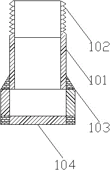
[0013] Such as figure 2 As shown, the flat nozzle includes a stainless steel tube 101, a stainless steel wire 103 and a stainless steel backing plate 104; the upper part of the stainless steel tube 101 is provided with an external thread 102; the stainless steel wire 103 is fixedly arranged outside the stainless steel tube 101 bottom; The stainless steel backing plate 104 is fixedly arranged under the stainless steel wire 103 .

[0014] In this embodiment, the stainless steel wire 103 is fixedly arranged outside the lower part of the stainless steel pipe 101 by welding.

[0015] In this embodiment, the stainless steel backing plate 104 is fixedly arranged under the stainless steel wire 103 by welding.

[0016] The middle of the stainl...


PUM


Abstract

The invention discloses a flat nozzle. The flat nozzle comprises a stainless steel pipe, a stainless steel wire and a stainless steel padding plate. The upper portion of the stainless steel pipe is provided with an external thread. The stainless steel wire is fixedly arranged outside the lower portion of the stainless steel pipe. The stainless steel padding plate is fixedly arranged below the stainless steel wire. A through hole is formed in the middle of the stainless steel padding plate. According to the flat nozzle, the flow quantity of the nozzle is increased, and debris in the diameter smaller than 15 mm can pass through the nozzle, so that the nozzle is not prone to blocking and the service life of the nozzle is prolonged.

Description

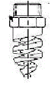
technical field [0001] The invention relates to a flat nozzle. Background technique [0002] Such as figure 1 As shown, the spiral nozzle is a solid cone or hollow cone spray nozzle, and the spray angle range can be 50°-170°; after the liquid (or slurry) passes through the tangent and collision with the continuously smaller spiral surface, it becomes It is sprayed into tiny droplets to form a mist. However, due to the spiral structure of the existing spiral, the water outlet of the nozzle is too small. When there is debris in the nozzle and the debris is larger than 6mm, the nozzle will be blocked, affecting the use of the nozzle, and even shortening the length of the nozzle. Nozzle life. [0003] Therefore, the prior art still needs to be improved and developed. Contents of the invention [0004] The purpose of the present invention is to provide a flat nozzle, which aims to solve the problem that the water outlet of the existing common spiral nozzle is too small, whi...

Claims


Application Information

Patent Timeline
IPC IPC(8): B05B1/06
CPCB05B1/00
Inventor 范永禧
Owner 范永禧
Learn More