
Lateral decubitus position fixing frame

A fixed frame and lateral position technology, applied in medical science, hospital beds, hospital equipment, etc., can solve problems such as failure to turn over, inability to effectively prevent pressure sores, difficulty in retracting, etc., to reduce the incidence of pressure sores, The effect of good nurse-patient relationship and reducing labor intensity

Inactive Publication Date: 2015-04-29
ENSHI ZUISHIZHOU TRADING
View PDF0 Cites 0 Cited by
  • Summary
  • Abstract
  • Description
  • Claims
  • Application Information

AI Technical Summary

Problems solved by technology

[0002] At present, in clinical nursing work, there are often many patients with disturbance of consciousness, hemiplegia or physical activity disorder and long-term bedridden patients who cannot turn over spontaneously due to various reasons or need to be forced to turn over due to the impact of the disease. Patient lying on the back is not supine, lying on the side is not lying on the side
What's more, twisted torso will not only fail to achieve the effect of turning over, but may also lead to aggravation of the condition. Therefore, when nursing similar patients, the nurse must not help the patient to turn over every 2 hours as usual, and must re-support the pad at most half an hour
When using a turning pillow, it must be cleaned frequently, especially for patients with wounds oozing blood on the back. It is easy to get dirty and wet, difficult to clean, dry and disinfect, which adds a certain amount of trouble to the nursing work.
It is not easy to retract and retract, resulting in untidy bed units; the use of disposable turn pads is airtight, does not absorb sweat, the angle cannot be adjusted, and the volume is large and difficult to retract. Also need to pay a certain fee, and the expenditure of the department is also large.
The above two not only fail to suspend the sacrum and leave the bed, but also put pressure on the sacrum, and cannot effectively prevent pressure sores

Method used


Image

  • Lateral decubitus position fixing frame

Examples


Embodiment

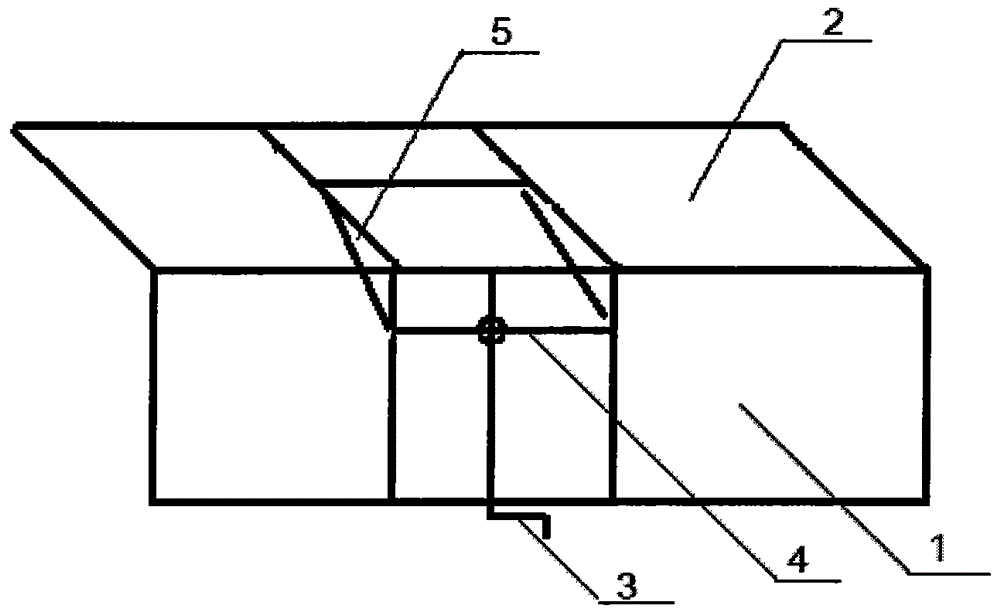
[0008] Embodiment: The lateral position fixed frame of the present invention comprises a base plate, a side frame and a rocker, and is characterized in that the side of the base plate 1 is loosely connected to the side frame 2, and the rocker arm 3 is arranged on the base plate 1 to connect the transverse link 4, and on the base plate 1 Connected with the side frame 2 by a support rod 5, the support rod 5 is connected on the cross link 4 on the base plate 1, and the cross link 4 is controlled by the rocker arm 3 to move forward and backward on the base plate 1 to drive the side frame 2 to move up and down. Bottom plate 1 side live connection side frame 2 is nut connection. The adjustable and foldable lateral position fixing bracket is composed of a 60cm long and 40cm wide porous stainless steel panel, a stainless steel threaded pipe, a stainless steel column, and 3 nuts. The perforated stainless steel panel is welded with steel columns to form side frames, and the bottom frame...


PUM


Abstract

The invention relates to a lateral decubitus position fixing frame which comprises a baseplate, a side frame and a rocker arm. The lateral decubitus position fixing frame is characterized in that a lateral side of the baseplate (1) is movably connected with the side frame (2), the rocker arm (3) is arranged on the baseplate (1) and connected with a transverse connecting rod (4), the baseplate (1) and the side frame (2) are connected by a supporting rod (5), the supporting rod (5) is connected on the transverse connecting rod (4) on the baseplate (1), and the transverse connecting rod (4) is controlled by the rocker arm (3) to move back and forth on the baseplate (1) to drive the side frame (2) to move up and down. By using the lateral decubitus position fixing frame, a patient can feel comfortable, the lateral decubitus position fixing frame is economical and practical, occurrence rate of pressure sores is lowered greatly, bed sheet position is clean and attractive, labor intensity of nursing personnel is reduced, expenditure cost of hospitals is lowered, and a good nurse-patient relation is established.

Description

technical field [0001] The invention relates to a foldable side-lying position fixing bracket, especially a side-lying position fixing bracket. Background technique [0002] At present, in clinical nursing work, there are often many patients with disturbance of consciousness, hemiplegia or physical activity disorder and long-term bedridden patients who cannot turn over spontaneously due to various reasons or need to be forced to turn over due to the impact of the disease. A patient lying on his back is not counted as lying on his back, and lying on his side is not counted as lying on his side. What's more, twisted torso will not only fail to achieve the effect of turning over, but may also lead to aggravation of the condition. Therefore, when nursing similar patients, nurses must not routinely help the patient turn over every 2 hours, and must re-support the pad within half an hour at most. When using a turning pillow, it must be cleaned frequently, especially for patients ...

Claims


Application Information

Patent Timeline
IPC IPC(8): A61G7/057A61G7/07
Inventor 刘耕
Owner ENSHI ZUISHIZHOU TRADING
Learn More