
Microscopic intraocular instrument

An instrument and head technology, applied in the field of microscopic intraocular scissors, can solve the problems of difficult operation, limited use range, inability to cut deep into the deep, and achieve the effect of reducing costs and improving sustainable utilization.

Inactive Publication Date: 2015-04-29
苏州贝尔一锋医疗器械有限公司
View PDF5 Cites 1 Cited by
  • Summary
  • Abstract
  • Description
  • Claims
  • Application Information

AI Technical Summary

Problems solved by technology

[0002] At present, the scissors used in ophthalmic surgery have been continuously improved and can be conveniently used in the operation. However, because the head structure of the scissors cannot get rid of the structural constraints of traditional scissors, it cannot cut deeply in small incisions, making its The scope of use is limited, which brings certain difficulties to the operation
For example, in the intracapsular intraocular lens implantation operation, the anterior capsule is usually torn open with micro forceps, so the operation is difficult, the safety performance is poor, and the success rate is low

Method used


Image

  • Microscopic intraocular instrument
  • Microscopic intraocular instrument
  • Microscopic intraocular instrument

Examples


Embodiment 1

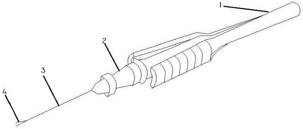
[0030] figure 1 It is a schematic diagram of the overall structure of the first embodiment of the microscopic intraocular device A according to the present invention.

[0031] Such as figure 1 As shown, in the first embodiment of the present invention, the microscopic intraocular instrument A includes a handle 1, a connecting part 2 and a head 3, and the handle 1 and the head 3 are fixedly arranged on the connecting part respectively. The two ends of the part 2, the handle 1 is detachably connected to the connecting part 2, the head 3 is detachably connected to the connecting part 2, the head 3 includes a pincer 4, and the The clamping scissors 4 include two parts of the scissors, and the two parts of the scissors are capable of relative displacement and jointly form a holding force.

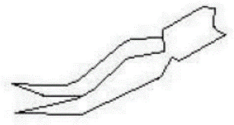
[0032] figure 2 for figure 1 Schematic diagram of the pinch zoom structure in .

[0033] Such as figure 2 As shown, in the first embodiment of the present invention, the clip scissors 4 ...

Embodiment 2

[0035] The difference between this embodiment and Embodiment 1 lies in the change of the structural shape of the clipper 4 .

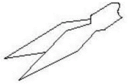
[0036] image 3 It is a schematic diagram of the clipping enlarged structure in the second embodiment of the microscopic intraocular instrument A according to the present invention.

[0037] Such as image 3 As mentioned above, in the second embodiment of the present invention, the clip scissors 4 in the microscopic intraocular instrument A are horizontal straight scissors 42, and the two parts of the scissors in the horizontal straight scissors 42 are in a straight line structure and are connected to each other. Symmetrical setting.

Embodiment 3

[0039] The difference between this embodiment and Embodiment 1 lies in the change of the structural shape of the clipper 4 .

[0040] Figure 4 It is a schematic diagram of the clipping enlarged structure in the third embodiment of the microscopic intraocular instrument A according to the present invention.

[0041] Such as Figure 4 As mentioned above, in the third embodiment of the present invention, the clipping scissors 4 in the microscopic intraocular instrument A are horizontal angle scissors 43, and the two parts of the horizontal angle scissors 43 are arranged in a misaligned position.


PUM


Abstract

The invention belongs to the field of surgical instruments, and in particular provides a microscopic intraocular instrument. The microscopic intraocular instrument comprises a handle, a connection part and a head part, wherein the handle and the head part are respectively fixed at two ends of the connection part; the handle and the connection part are detachably connected; the head part and the connection part are detachably connected; the head part comprises tongs; the tongs comprise two scissoring bodies; and the two scissoring bodies can displace relatively so as to form clamping force together. The microscopic intraocular instrument disclosed by the invention provides a plurality of different head part scissor structures, therefore, different surgical and operation requirements can be satisfied; furthermore, because various parts in the microscopic intraocular instrument are detachably connected with each other, a part of parts can be only changed or replaced in need of changing or replacing a certain part, the whole body of the microscopic intraocular instrument is unnecessary to change or replace, and thus, the sustainable utilization rate can be greatly increased.

Description

technical field [0001] The invention belongs to the field of surgical instruments, and more specifically, the invention belongs to a microscopic intraocular scissors used in ophthalmology. Background technique [0002] At present, the scissors used in ophthalmic surgery have been continuously improved and can be conveniently used in the operation. However, because the head structure of the scissors cannot get rid of the structural constraints of traditional scissors, it cannot cut deeply in small incisions, making its The scope of use is limited, which brings certain difficulties to the operation. For example, in the intracapsular intraocular lens implantation operation, the anterior capsule is usually torn open with micro forceps, so the operation is difficult, the safety performance is poor, and the success rate is low. In some vitreous cutting and intraball foreign body removal operations, if the scissors can be cut deep into the ball, the safety and reliability of the o...

Claims


Application Information

Patent Timeline
Patent Type & Authority Applications(China)
IPC IPC(8): A61F9/007
Inventor 李菊敏
Owner 苏州贝尔一锋医疗器械有限公司
Learn More