
Automatic towel drying device

A technology for drying devices and towels, which can be applied to home appliances, etc., can solve the problems of inconvenient installation, inaccurate control, and high cost, and achieve the effects of precise control, good energy saving effect, and low preparation cost

Inactive Publication Date: 2015-04-29
黄富华
View PDF8 Cites 2 Cited by
  • Summary
  • Abstract
  • Description
  • Claims
  • Application Information

AI Technical Summary

Problems solved by technology

[0002] The towel rack is an indispensable small furniture in daily life. With the improvement of people's quality of life, people have higher and higher functional requirements for it. A single drying function can no longer satisfy people's pursuit of a clean, healthy and comfortable life. ; Therefore, the electric drying towel rack has also become the general trend
However, the drying control methods of towel racks on the market are generally controlled by timing, because the humidity varies, and this control is not accurate; in addition, there are also humidity sensors to control, which are expensive and inconvenient to install
[0003] A towel rack with precise control, convenient installation and reliable control is an indispensable item in daily life; with the rapid development of modern science and technology, people's material living standards are improving day by day, intelligent control of towel dryers, drying Efficiency, drying quality, and operating costs, especially higher requirements for the automation of home appliances. Obviously, the existing towel drying technology cannot be realized, resulting in towel dryers (racks) products that have not been fully promoted so far.

Method used


Image

  • Automatic towel drying device

Examples


Embodiment 1

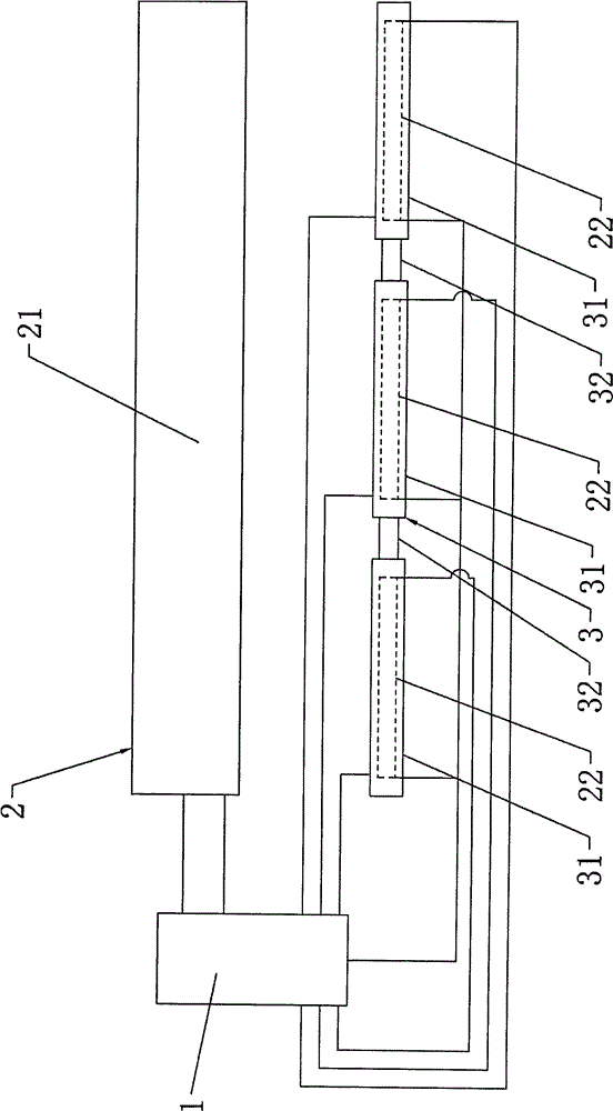
[0022] Embodiment 1, an automatic towel drying device, including a controller 1, a drying assembly 2, and a towel rack 3 for hanging towels. The towel rack 3 includes at least two conductive parts 31 arranged at intervals in sequence. An insulating part 32 is provided between two adjacent conductive parts 31 , and the drying assembly 2 and each conductive part 31 are respectively electrically connected to the controller 1 . Among them, the conductive part 31 is made of aluminum alloy material, that is, the conductive part 31 is an aluminum alloy conductive part, and the length of the conductive part 31 is 220mm; the insulating part 32 is made of plastic material, and the insulation cannot be used to connect two adjacent The plastic joint of the conductive part 31; at this time, the towel hanging part of the towel rack 3 is arranged in a group of aluminum alloy conductive part-plastic joint-aluminum alloy conductive part-plastic joint-aluminum alloy conductive part, totally 4 gr...

Embodiment 2

[0026] Embodiment 2, an automatic towel drying device, including a controller 1, a drying assembly 2, and a towel rack 3 for hanging towels. The towel rack 3 includes at least two conductive parts 31 arranged at intervals in sequence. An insulating part 32 is provided between two adjacent conductive parts 31 , and the drying assembly 2 and each conductive part 31 are respectively electrically connected to the controller 1 . Among them, the conductive part 31 is made of stainless steel material, that is, the conductive part 31 is a stainless steel conductive part, and the length of the conductive part 31 is 100mm; the insulating part 32 is made of plastic material, and the insulation cannot be used to connect two adjacent conductive parts. 31 plastic connector; at this time, the towel hanging part of the towel rack 3 is arranged into a group of stainless steel conductive part-plastic connector-stainless steel conductive part-plastic connector-stainless steel conductive part, tot...

Embodiment 3

[0030] Embodiment 3, an automatic towel drying device, including a controller 1, a drying assembly 2, and a towel rack 3 for hanging towels. The towel rack 3 includes at least two conductive parts 31 arranged at intervals in sequence. An insulating part 32 is provided between two adjacent conductive parts 31 , and the drying assembly 2 and each conductive part 31 are respectively electrically connected to the controller 1 . Among them, the conductive part 31 is made of aluminum alloy material, that is, the conductive part 31 is an aluminum alloy conductive part, and the length of the conductive part 31 is 220mm; the insulating part 32 is made of plastic material, and the insulation cannot be used to connect two adjacent The plastic joint of the conductive part 31; at this time, the towel hanging part of the towel rack 3 is arranged in a group of aluminum alloy conductive part-plastic joint-aluminum alloy conductive part-plastic joint-aluminum alloy conductive part, totally 4 gr...


PUM


Abstract

The invention discloses an automatic towel drying device. The automatic towel drying device comprises a controller, a drying assembly and a towel rack. The towel rack comprises at least two electric conduction parts, wherein an insulating part is arranged between every two adjacent electric conduction parts. The drying assembly and the electric conduction parts are all electrically connected with the controller. Due to the fact that the electric conduction performance of a wet towel is better than the electric conduction performance of a dry towel, when the wet towel is hung on the towel rack, the electric conduction parts making contact with the wet towel can be connected. Once the electric conduction parts are connected, the controller receives an electric conduction part connection signal and controls the drying assembly to be turned on, and the resistance value of the wet towel gradually increases when the wet towel is gradually dried; when the resistance value of the towel reaches the resistance value set by the controller, the controller receives a resistance value signal and controls the drying assembly to be turned off. Through the structural design, the control process is controlled through the correlation between the humidity of the towel and electric conduction, and the automatic towel drying device is novel in design, simple in structure, accurate and convenient to control, low in manufacturing cost and good in energy saving effect.

Description

technical field [0001] The invention relates to the technical field of drying devices, in particular to an automatic towel drying device. Background technique [0002] The towel rack is an indispensable small furniture in daily life. With the improvement of people's quality of life, people have higher and higher requirements for its functions. A single drying function can no longer satisfy people's pursuit of a clean, healthy and comfortable life. ; Therefore, the electric drying towel rack has also become the general trend. However, the drying control methods of towel racks on the market are generally controlled by timing, because the humidity varies, and this control is not accurate; in addition, humidity sensors are also used for control, which is expensive and inconvenient to install. [0003] A towel rack with precise control, convenient installation and reliable control is an indispensable item in daily life; with the rapid development of modern science and technology...

Claims


Application Information

Patent Timeline
Patent Type & Authority Applications(China)
IPC IPC(8): A47K10/06
Inventor 杨兵霞
Owner 黄富华
Learn More