Lock for a motor vehicle

A technology for motor vehicles and car locks, applied in electric car locks, electric locks, vehicle locks, etc., can solve problems such as low efficiency, and achieve the effects of reduced wear and material costs

Inactive Publication Date: 2015-04-22
BROSE SCHLIESSSYSTEME GMBH & CO KG
View PDF7 Cites 4 Cited by
  • Summary
  • Abstract
  • Description
  • Claims
  • Application Information

AI Technical Summary

Problems solved by technology

However, the disadvantage of the direct drive there is its lower efficiency

Method used


Image

  • Lock for a motor vehicle
  • Lock for a motor vehicle
  • Lock for a motor vehicle

Examples


Embodiment Construction

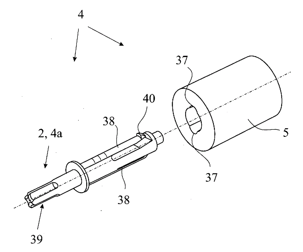
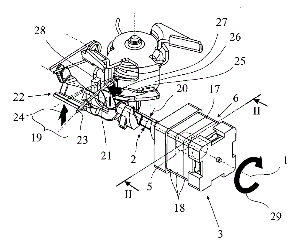
[0032] It should be noted in advance that only the components of the proposed motor vehicle lock that are necessary for the explanation of the teaching are shown in the drawings. Correspondingly, the drawing does not show a locking pin (Schlossfalle), which usually cooperates with a locking bolt (Schliessbolzen) or the like and which is held in the main closing position and in a possible pre-closing position by means of a locking pawl (Sperrklinke) in position.

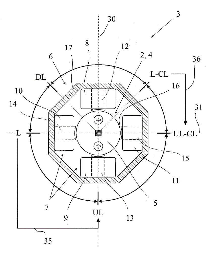
[0033] The motor vehicle lock has an adjusting element 2 which is adjustable about an adjusting element axis 1 and a drive 3 for adjusting the adjusting element 2 . The drive 3 is used to set different functional states of the motor vehicle lock, which will be explained in more detail below. Important for the presented teaching is primarily the basic design of the adjusting element 2 and the drive 3 . figure 1 and 2 shows that the drive 3 has a rotor formed by an adjusting element 2 with an approximately cylindrica...


PUM


Abstract

A motor-vehicle lock with an adjusting element, which is adjustable about an adjusting element axis, and a drive for the adjustment of the adjusting element, the drive having a rotor, formed by the adjusting element, with a permanent magnet arrangement and a stator with a coil arrangement-comprising at least two coils, and the drive being designed in the manner of a direct drive. It is proposed that the stator has at least two poles, by way of which a magnetic field generated by the coil arrangement is made to pass, in that at least one pole of the stator reaches up to the rotor to within a gap which in cross section is essentially in the form of a segment of a ring, and in that the poles of the stator are magnetically coupled by way of a conducting arrangement running around the rotor with respect to the adjusting element axis.

Description

technical field [0001] The invention relates to a motor vehicle lock according to the preamble of claim 1 and a method for actuating such a motor vehicle lock according to the preamble of claim 20 as well as a method according to the preamble of claim 26 Methods. Background technique [0002] The motor vehicle lock in question is used in all types of motor vehicle locking elements. This applies in particular to side doors, rear doors, rear lids, luggage compartment lids or engine hoods. In principle, these locking elements can also be designed in the form of sliding doors. [0003] Today's motor vehicle locks are equipped with a series of functions which can be activated motorized by means of electric drives. The challenge is always to make the drives as compact as possible. [0004] The known motor vehicle lock (DE 10 2008 012 563) from which the invention is based has a drive for the adjustable functional element, which is designed in the form of a direct drive. A dis...

Claims


Application Information

Patent Timeline
IPC IPC(8): E05B81/04H02K37/16
CPCE05B77/26E05B2015/0496E05B81/16H02K37/14E05B81/90Y10T70/7057E05B81/42E05B81/06E05B77/28
Inventor D. 凯斯勒T. 德赖曼A. 博戈拉茨J. 赖纳特A. 埃尔-哈穆米
Owner BROSE SCHLIESSSYSTEME GMBH & CO KG
Why Eureka
Try Eureka