Filter method and filter circuit applied to eps power supply system
A power supply system and filter circuit technology, which is applied in the direction of electrical components, impedance networks, digital technology networks, etc., can solve problems such as temperature drift noise, susceptibility to interference, and many system components, and achieve low-frequency interference and eliminate low-frequency interference.
- Summary
- Abstract
- Description
- Claims
- Application Information
AI Technical Summary
Problems solved by technology
Method used
Image
Examples
Embodiment 1
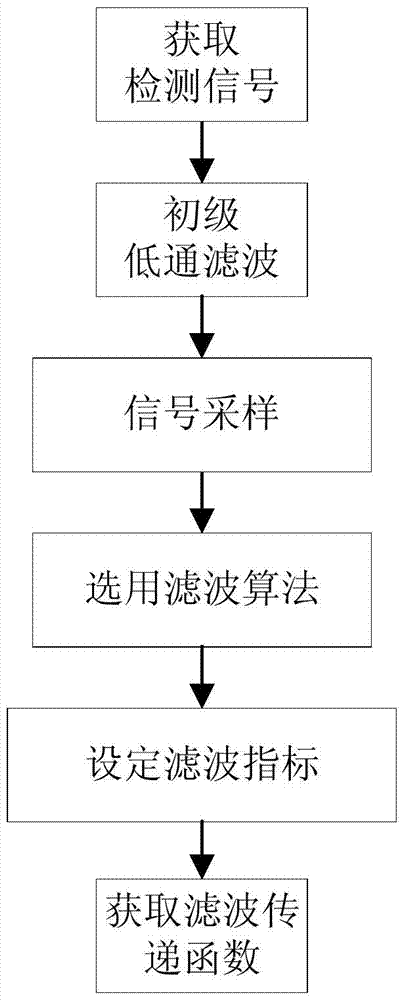
[0064] In the above, in step B of the debugging process and filtering process, high frequency components higher than 500HZ-1000HZ in the detection signal are filtered out; in step C, A / D sampling is performed on the detection signal at a frequency that is at least twice the highest frequency of the detection signal .
[0065] Since the filtering of the EPS power system is mainly the low-frequency part of the signal, in order to maximize the frequency band of the required detection signal and reduce the amount of data calculation for subsequent digital filtering. After a lot of experiments, it is found that the effect of pre-filtering the high-frequency components of 500HZ-1000HZ of the detection signal is the best. The subsequent detection signal sampling is obtained according to the Shannon sampling theorem.
Embodiment 2
[0067] In the above, step F of the debugging process specifically includes,
[0068] F1) Put the detection signal after A / D sampling into the data buffer area;
[0069] F2) obtain the transfer function of the Ellipt low-pass filter algorithm satisfying filter index by approximation method;
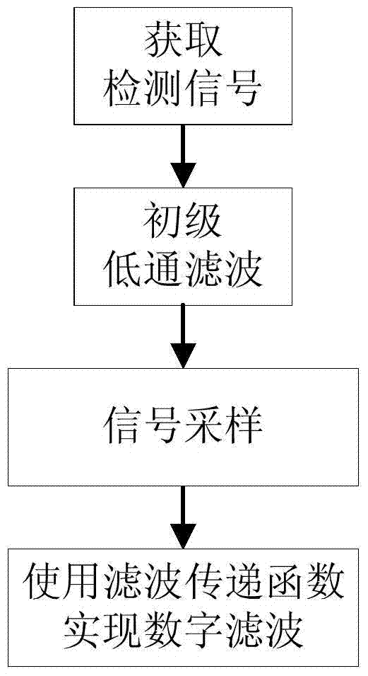
[0070] Step D of the filtering process specifically includes,
[0071] D1) storing the detection signal after A / D sampling in the data buffer area;
[0072] D2) Apply the transfer function of the Ellipt low-pass filter algorithm obtained in the debugging process to digitally filter the detection signal.
[0073] This embodiment provides a method suitable for obtaining and executing the transfer function of a specific Ellipt low-pass filter algorithm. Traditionally, the transfer function of the elliptic filter is a relatively complex function. If the traditional design method is used to synthesize the circuit network, cumbersome calculations must be performed, and table lookups must be p...
Embodiment 3
[0075] In the above, steps D-F of the debugging process are implemented by a computer; step D of the filtering process is implemented by a DSP processor. The approximation of the transfer function of the Ellipt low-pass filter algorithm can be realized by an external computer due to the large amount of processing. For example, MATLAB running on a computer can design an elliptic filter, which can greatly simplify the design process.
PUM
 Abstract
Description
Claims
Application Information
 - R&D
- Intellectual Property
- Life Sciences
- Materials
- Tech Scout
- Unparalleled Data Quality
- Higher Quality Content
- 60% Fewer Hallucinations
Browse by: Latest US Patents, China's latest patents, Technical Efficacy Thesaurus, Application Domain, Technology Topic, Popular Technical Reports.
© 2025 PatSnap. All rights reserved.Legal|Privacy policy|Modern Slavery Act Transparency Statement|Sitemap|About US| Contact US: help@patsnap.com


