
Transfer printing plate, display screen, display device and display device manufacturing method

A technology of display screen and transfer plate, applied in the direction of instruments, nonlinear optics, optics, etc., can solve the problems of PanelID marking work, occupancy, and reduction of production line efficiency.

Inactive Publication Date: 2015-04-22
HEFEI BOE OPTOELECTRONICS TECH +1
View PDF6 Cites 19 Cited by
  • Summary
  • Abstract
  • Description
  • Claims
  • Application Information

AI Technical Summary

Problems solved by technology

When the number of unit displays in a template glass is small, the marking work of Panel ID is relatively simple and occupies less capacity of the production line; but when the number of unit displays on a mother glass is large, the Panel ID The marking work will be more cumbersome and take up more production line capacity
Especially at present, the size of unit displays made by each panel generation line is getting smaller and smaller. There are hundreds of unit displays on the substrate on a mother glass, and the work of marking Panel ID becomes more difficult.
Sometimes, for the consideration of production line capacity, the Panel ID is not marked, so that the problems in the subsequent production process cannot be traced back to the previous process, which greatly reduces the efficiency of the production line

Method used


Image

  • Transfer printing plate, display screen, display device and display device manufacturing method
  • Transfer printing plate, display screen, display device and display device manufacturing method
  • Transfer printing plate, display screen, display device and display device manufacturing method

Examples


Embodiment Construction

[0044] The principles and features of the present invention are described below in conjunction with the accompanying drawings, and the examples given are only used to explain the present invention, and are not intended to limit the scope of the present invention.

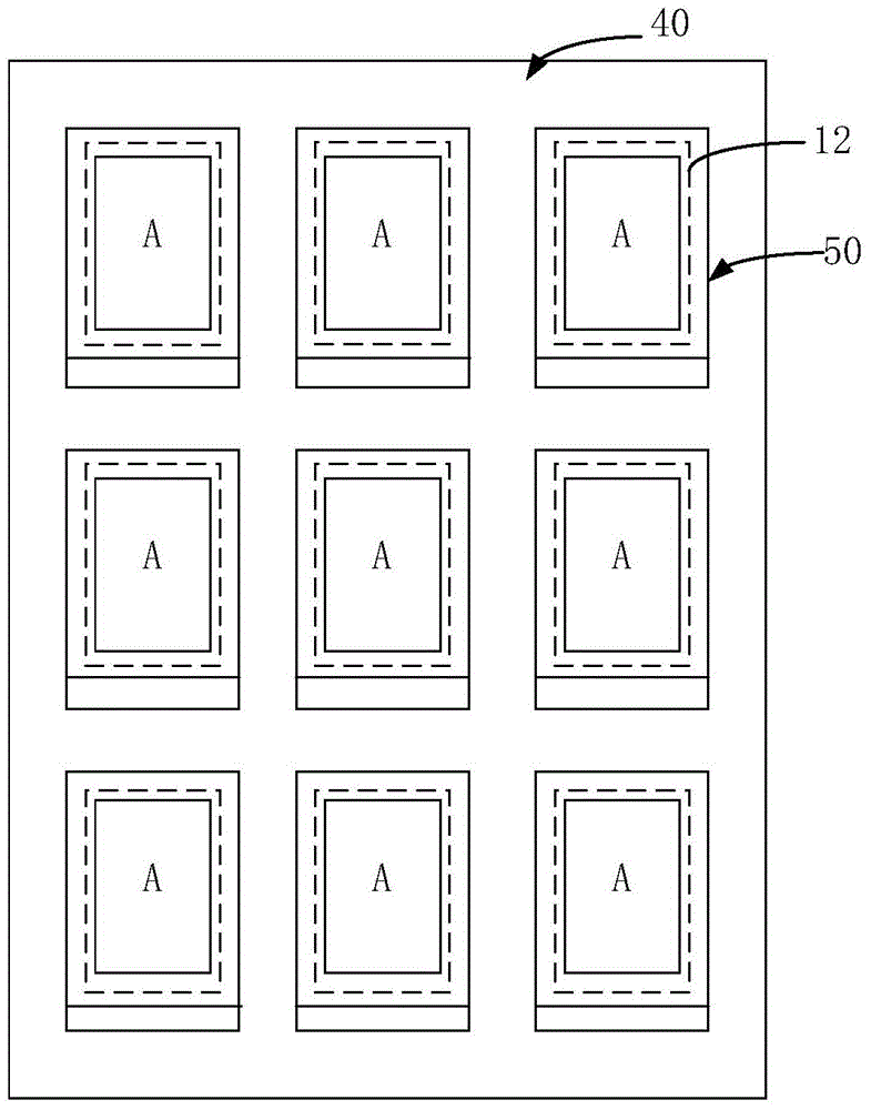
[0045] Aiming at the technical problems of the prior art, such as the cumbersome work of identifying the Panel ID of the unit display screen on the motherboard and taking up more production line capacity, the present invention provides a transfer board, a display screen, a display device, and a manufacturing method for the display device. It can improve the efficiency of marking unit display screens in the current production line, and effectively improve the production line production capacity through simple design changes.

[0046] Such as Figure 5 As shown, the transfer plate provided by the present invention is used to form an alignment film on a motherboard with multiple unit display screens; the transfer plate...


PUM


Abstract

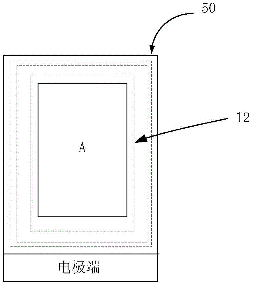
The invention provides a transfer printing plate, a display screen, a display device and a display device manufacturing method. The transfer printing plate comprises a printing region and a non-printing region, wherein the printing region comprises multiple sub-printing units corresponding to multiple unit display screens on a mother plate in one-to-one mode, different mark zones are arranged on each sub-printing unit respectively and used for forming marks for identifying the unit display screens on the mother plate on the unit display screens while forming alignment films on the unit display screens on the mother plate. By means of the scheme, the mark zones are set in the printing region of the transfer printing plate through improvement on the transfer printing plate structure, the unit display screens can be simultaneously marked on the same mother plate when the alignment films are formed on the mother plate, and the unit display screen marking efficiency of a current production line is improved.

Description

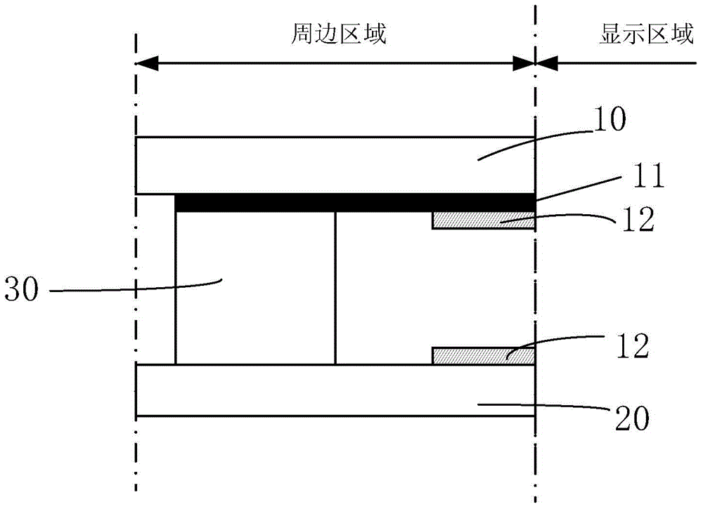
technical field [0001] The invention relates to the field of display technology, in particular to a transfer plate, a display device and a manufacturing method of the display device. Background technique [0002] In the field of display technology, liquid crystal displays are widely used due to their advantages of small size, low power consumption, no radiation, and high resolution. figure 1 is a schematic cross-sectional view of the peripheral area of ​​a liquid crystal display. Such as figure 1 As shown, a general liquid crystal display includes a color filter substrate 10 and an array substrate 20 disposed opposite to each other, and a liquid crystal layer (not shown in the figure) between the two substrates. The surroundings of the color filter substrate 10 and the array substrate 20 are connected by a sealant 30 , the color filter substrate 10 has a black matrix 11 and an alignment film 12 , and the array substrate has an alignment film 12 . Among them, the display a...

Claims


Application Information

Patent Timeline
IPC IPC(8): G02F1/1337G02F1/1333
CPCG02F1/1303G02F1/1337G02F1/1333G02F1/133351G02F1/133354G02F1/1341
Inventor 王辉王春陈俊生李小和车春城
Owner HEFEI BOE OPTOELECTRONICS TECH
Learn More