
Circuit board testing tool

A technology for testing tooling and circuit boards. It is applied in the direction of electronic circuit testing and measuring device casings. It can solve problems such as inability to connect circuit board testers and circuit board test points, achieve fast and accurate connections, and improve detection speed.

Inactive Publication Date: 2015-04-22
CHONGQING CHANGYE AUTO PARTS
View PDF10 Cites 13 Cited by
  • Summary
  • Abstract
  • Description
  • Claims
  • Application Information

AI Technical Summary

Problems solved by technology

[0005] In view of this, the purpose of the present invention is to provide a circuit board testing tool to solve the problem in the prior art that the circuit board tester cannot be quickly connected to each test point on the circuit board

Method used


Image

  • Circuit board testing tool

Examples


Embodiment Construction

[0012] The present invention will be further described below in conjunction with the accompanying drawings and embodiments.

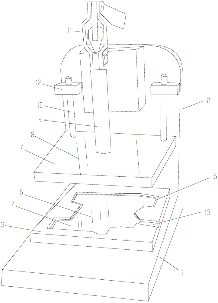
[0013] As shown in the figure, the circuit board testing tooling of this embodiment includes an L-shaped base composed of a horizontal plate 1 and a vertical plate 2, and a lower template 3 is arranged on the horizontal plate, and the lower template is provided with A positioning groove 4 matching the outer contour of the circuit board, a step 5 supporting the circuit board is provided on the groove wall of the positioning groove, and a first probe connected to a detection point on the lower surface of the circuit board is provided on the groove bottom of the positioning groove Group 6;

[0014] It also includes an upper template 7, which is provided with a second probe group 8 connected to the detection point on the upper surface of the circuit board, and is also provided with a connecting rod 9 and a guide rod 10 on the upper template. A handle 11 fo...


PUM


Abstract

The invention discloses a circuit board testing tool which comprises an L-shaped pedestal and a lower die plate. The lower die plate is provided with a positioning groove, and the bottom of the positioning groove is provided with a first probe group that is connected with detection points at the lower surface of the circuit board. An upper die plate is also included, the upper die plate is provided with a second probe group that is connected with detection points at the upper surface of the circuit board, a connecting rod and guide rods, and a vertical plate is provided with a handle which can drive the connecting rod to move up and down and guiding blocks which are in up-and-down sliding cooperation with the guide rod. During detection, the circuit board is placed in the positioning groove, the positioning groove can ensure that the detection points at the detection points at the lower surface of the circuit board are correctly connected with the upper ends of first probe group, the handle pushes the upper die plate to move downwardly, the second probe group on the upper die plate is correctly connected with the detection points at the upper surface of the circuit board, the detection points of the circuit board are rapidly and accurately connected with a circuit board detector via the tool, and the circuit board detection speed is greatly improved.

Description

technical field [0001] The invention relates to a tooling, in particular to a circuit board testing tooling. Background technique [0002] In the production process of the car navigator, it is very important to test the circuit board in the car navigator. [0003] In the prior art, for circuit boards produced in small batches, the voltage and current between two measurement points on the circuit board are generally directly tested with a multimeter to determine whether the circuit board is qualified. This test method has the disadvantage of low test efficiency. [0004] For circuit boards produced in large quantities, in the prior art, a circuit board tester is generally used for automatic detection by software programs. The method of use is to connect each test point on the circuit board to the signal input terminal on the circuit board tester, run the test program in the computer, and the test result will be displayed on the computer monitor. If it is good, it will show O...

Claims


Application Information

Patent Timeline
IPC IPC(8): G01R31/28G01R1/04
Inventor 陈大平李航高静
Owner CHONGQING CHANGYE AUTO PARTS
Learn More