
Polluted soil in-situ solidification/stabilization treatment device

A technology of stabilization treatment and in-situ solidification, which is applied in the field of contaminated site restoration engineering, can solve problems such as difficulty in applying hard contaminated soil restoration, affecting the stabilization effect of pollutants, and failing to meet the needs of the project. Reasonable, the effect of reducing the processing cost

Pending Publication Date: 2015-04-22
INST OF ROCK AND SOIL MECHANICS - CHINESE ACAD OF SCI +1
View PDF6 Cites 31 Cited by
  • Summary
  • Abstract
  • Description
  • Claims
  • Application Information

AI Technical Summary

Problems solved by technology

For example, the Chinese Patent Authorization Announcement No. CN 202449974U, the authorized announcement date was September 26, 2012, disclosed a patent document of a utility model titled sludge in-situ solidification device. The stirring head of the device is mechanically driven, and the length of the stirring head is limited. , the depth of in-situ treatment is limited, and it is difficult to treat the soil with certain gravel, which cannot meet the needs of the project
For example, the Chinese Patent Authorization Announcement No. CN 103046538 B, the authorized announcement date was October 15, 2014, disclosed a patent document of a utility model titled an in-situ solidification and stabilization treatment system for polluted soil. , the mixing head is directly stirred in the polluted soil, which is difficult to apply to the restoration of hard polluted soil. The medicine and water agent are directly added to the polluted soil, which is a serious waste. At the same time, impurities such as stones and plastics in the polluted soil will reduce the curing strength , seriously affecting the stabilization effect of pollutants

Method used


Image

  • Polluted soil in-situ solidification/stabilization treatment device

Examples


Embodiment Construction

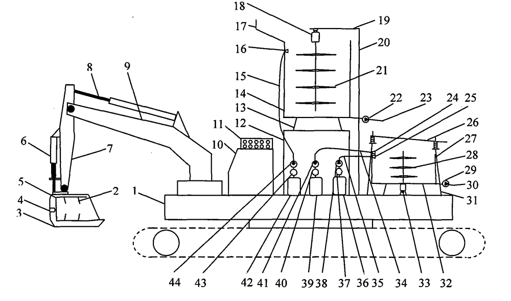
[0010] Attached below picture The present invention is described in further detail:

[0011] See attached picture , An in-situ solidification / stabilization treatment equipment for polluted soilIt consists of a crawler excavator 1, a screening and crushing system, a mixing system, a chemical supply system, a soil treatment system, an operation control system and pipelines. The screening and crushing system is set at the front end of the crawler excavator 1. The screening and crushing The system consists of a screening and crushing bucket, a first hydraulic rod 6, a first excavating arm 7, a second hydraulic rod 8, and a second excavating arm 9, wherein the screening and crushing bucket consists of a crushing device 2, a bucket frame 3, The first motor 4 and the rotary screen 5 are composed, the bucket frame 3 is in the shape of a hollow square frame, the first motor 4 is fixed on the bottom of the bucket frame 3, the first motor 4 is connected with the rotary screen 5 throu...


PUM


Abstract

The invention relates to a polluted soil in-situ solidification / stabilization treatment device, and belongs to the technical field of polluted site restoration work. The polluted soil in-situ solidification / stabilization treatment device is composed of a crawler excavator, a screening and crushing system, a stirring system, a soil treatment system, a chemical supply system, an operation control system and a pipeline. The screening and crushing system can crush hard soil blocks in polluted soil and screen out stones, plastic and other impurities in the polluted soil, the device can adapt to construction under complex working conditions, and meanwhile continuous operation of the stirring system is guaranteed. The soil treatment system can further remove large-particle matter in the polluted soil, the polluted soil treatment capacity is reduced, and treatment cost is saved. All chemical bins and equipment are integrated on the crawler excavator, and transport and construction are convenient. The polluted soil in-situ solidification / stabilization treatment device integrates earth excavation, soil screening, chemical adding, uniform stirring, site formation and automatic control, and is compact in structure, convenient to operate and high in adaptability and efficiency.

Description

technical field [0001] The invention relates to in-situ solidification / stabilization treatment equipment for polluted soil, belonging to the technical field of polluted site restoration engineering. Background technique [0002] With the development of my country's social economy and the acceleration of urbanization, a large number of legacy polluted land needs to be treated urgently. According to the National Soil Pollution Survey Bulletin released by the Ministry of Environmental Protection in 2014, the overall soil environment situation in the country is not optimistic. Some areas have serious soil pollution, the soil environment quality of cultivated land is worrying, and the soil environment problems of industrial and mining wasteland are prominent. Man-made activities such as industry, mining, agriculture, and high background values ​​of the soil environment are the main causes of soil pollution or exceeding standards. According to statistics, there are about 150 mill...

Claims


Application Information

Patent Timeline
IPC IPC(8): E02D3/00E02D3/12B09C1/08
CPCE02D3/00E02D3/12E02D3/126E02F3/301E02F3/40E02F5/30E02F5/305B09C1/08
Inventor 薛强李江山张亭亭王平陈亿军王富
Owner INST OF ROCK AND SOIL MECHANICS - CHINESE ACAD OF SCI
Learn More