Novel efficient twisting device

A twister and high-efficiency technology, which is applied in the field of air suction and cleaning devices of strip coilers, can solve the problems of short service life and poor wear resistance, and achieve the effects of increasing service life, improving wear resistance and improving twisting effect

Inactive Publication Date: 2015-04-22
JIANGSU TAIDA TEXTILE
View PDF0 Cites 1 Cited by
  • Summary
  • Abstract
  • Description
  • Claims
  • Application Information

AI Technical Summary

Problems solved by technology

The traditional rubber twister is made of black rubber, which has poor wear resistance and short service life

Method used


Image

  • Novel efficient twisting device

Examples


Embodiment Construction

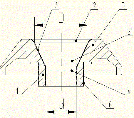
[0013] The present invention will be further described below based on the drawings and the embodiments.

[0014] The new high-efficiency twister shown in the figure includes an upper conical ring 5 and a lower shaft sleeve 1 which are connected as a whole; the conical ring 5 and the shaft sleeve 1 are provided with a yarn top hole 2 from top to bottom. , Twisting hole 3, Twist releasing hole 4; Yarn top hole 2, Twisting hole 3, Twisting hole 4 The hole wall is provided with a wear-resistant layer Ⅰ7, and the outer wall of the sleeve 1 is provided with a wear-resistant layer Ⅱ6; Twisting hole 3 The hole diameter D is twice the hole diameter d of the release hole 4.


PUM


Abstract

The invention discloses a novel efficient twisting device. The novel efficient twisting device comprises a tapered ring at the upper part, and a shaft sleeve at the lower part; the tapered ring and the shaft sleeve are integrated; a yarn feeding propping hole, a twisting hole and a releasing hole are formed in the tapered ring and the shaft sleeve from top to bottom; wearable layers I are arranged on the walls of the yarn feeding propping hole, the twisting hole and the releasing hole. The novel efficient twisting device is characterized in that a wearable layer II is arranged on the outer wall of the shaft sleeve; the diameter D of the twisting hole is 2 times the diameter d of the releasing hole. The novel efficient twisting device is high in wear resistance, long in service life, and high in twisting effect.

Description

Technical field [0001] The invention relates to the field of textile machinery, in particular to an air suction cleaning device for a spool machine. Background technique [0002] After the roving frame is drafted, the structure of the beard output from the front roller is loose, and the fibers can be tightly entangled by twisting, which can meet the requirements of winding and forming. In order to prevent accidental elongation and end breakage during the winding process, and reduce the unevenness of roving evenness and quality, false twisting is usually used to enhance the strength of the spinning section. The direct choice of false twist effect affects the yield and quality of the yarn. The traditional rubber twister is made of black rubber, which has poor wear resistance and short service life. Summary of the invention [0003] Aiming at the shortcomings of the prior art, the utility model proposes a new high-efficiency twister which can significantly improve the wear resistan...

Claims


Application Information

Patent Timeline
Patent Type & Authority Applications(China)
IPC IPC(8): D01H7/00
CPCD01H7/92
Inventor 李顺喜金爱国黄智鹏王跃明
Owner JIANGSU TAIDA TEXTILE
Why Eureka
Try Eureka