A vertical coating fixture

A vertical placement and fixture technology, used in sputtering, ion implantation, vacuum evaporation, etc., can solve problems such as poor mirror surface shape accuracy, and achieve the effect of easy installation and simple operation

Active Publication Date: 2017-02-01
INST OF OPTICS & ELECTRONICS - CHINESE ACAD OF SCI
View PDF5 Cites 0 Cited by
  • Summary
  • Abstract
  • Description
  • Claims
  • Application Information

AI Technical Summary

Problems solved by technology

[0003] The purpose of the present invention is to provide a coating fixture for the vertical placement of the mirror body during the coating process, which can solve the problem of poor surface shape accuracy of the mirror coated by the vertical coating machine

Method used


Image

  • A vertical coating fixture
  • A vertical coating fixture
  • A vertical coating fixture

Examples


example example 1

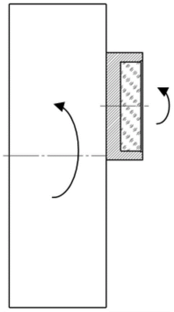
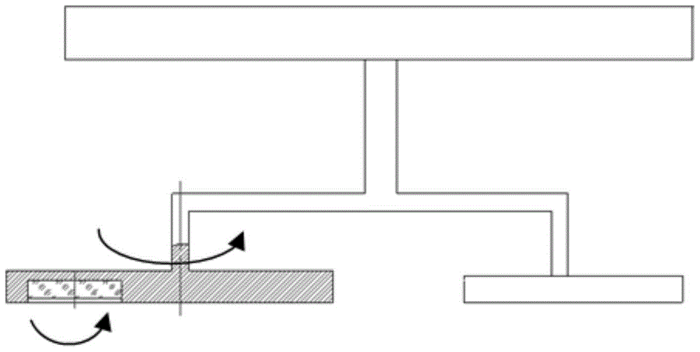
[0021] A kind of vertically placed coating fixture of this embodiment, such as Figure 1a , 1b , Figure 2 ~ Figure 6 shown.

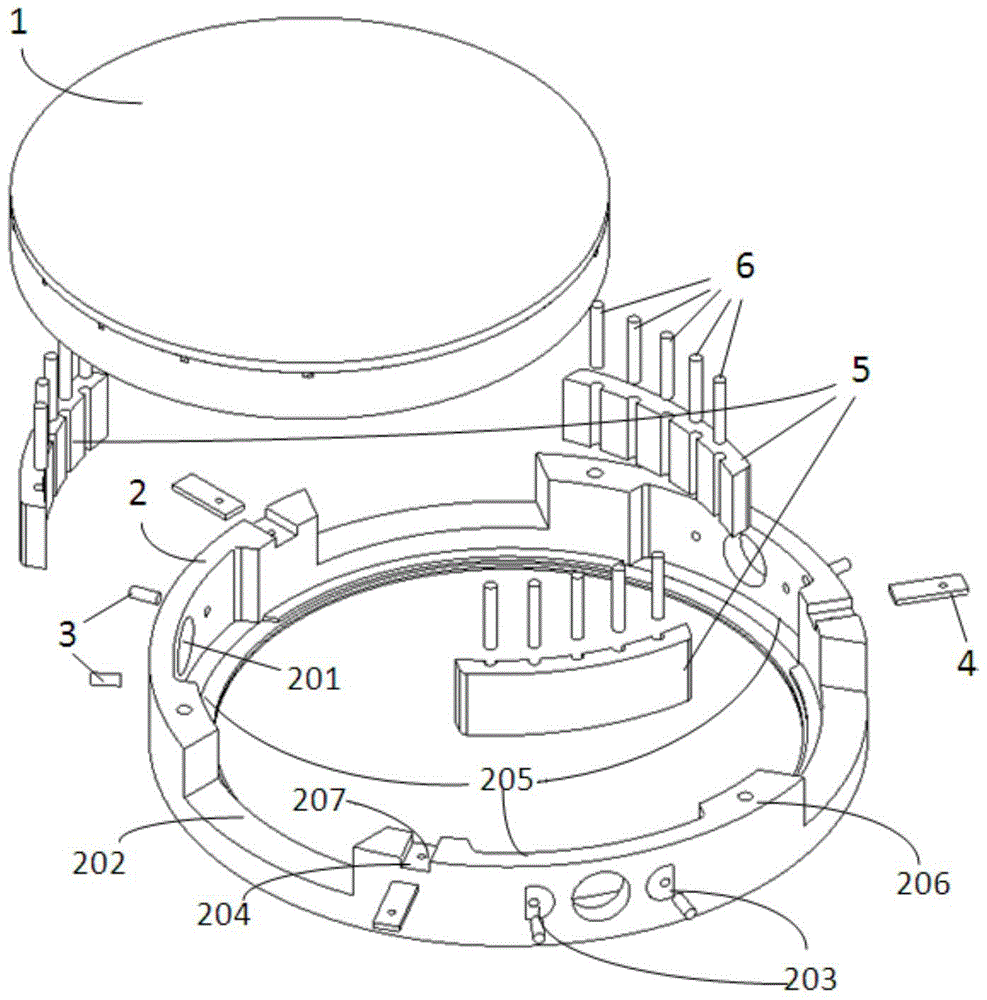
[0022] All components of this embodiment such as figure 2 shown. The object to be coated is mirror 1, such as image 3 As shown, its structure is a hollow structure with poor rigidity. The fixture main body 2 is a ring-shaped shell, and the reflector 1 is placed in the inner cavity of the fixture main body 2. There are three arc-shaped cushion blocks 5 uniformly distributed at 120° on the inner surface of the fixture main body 2, and the outer circle of the arc-shaped cushion block 5 The arc surface 502 matches the three inner cavity contours 205 of the clamp body 2 , and the inner arc surface 501 matches the outer diameter contour of the mirror 1 . There are 6 jacking screws 3 radially distributed on the side part of the main body of the fixture, which are used to adjust the gap between the arc-shaped pad 5 and the reflector 1 to clamp the refle...


PUM


Abstract

The invention discloses a vertically-placed coating clamp. The main part of the coating clamp is a clamp body, the clamp body is an annular shell, an inner cavity of the clamp body is used for placing a reflecting mirror to be coated, and the to-be-coated face of the reflecting mirror is placed downwards. Three threaded holes which are evenly distributed by 120 degrees are formed in the clamp body, and the three threaded holes are connected with the working table board of a coating machine. Three blocking sheets which are evenly distributed by 120 degrees are further arranged on the clamp body, so that the reflecting mirror is prevented from being disengaged from the inside of the coating clamp in the coating process. Three arc-shaped cushion blocks which are evenly distributed by 120 degrees are arranged on the inner side face of the clamp body, the outer arc surfaces of the cushion blocks are matched with the contour of the inner cavity of the clamp body, and the inner arc surfaces of the cushion blocks are matched with the outer-diameter contour of the reflecting mirror. Six jackscrews are distributed on the side face of the clamp body in a radial shape and are used for adjusting the gaps between the cushion blocks and the reflecting mirror so as to clamp the reflecting mirror. The vertically-placed coating clamp solves the problem that when a mirror body vertically-placed coating machine is used for plating a reflecting mirror face with poor rigidity, the precision is poor.

Description

technical field [0001] The invention relates to the coating field, in particular to a vertically placed coating fixture. Background technique [0002] Optical thin films are an important part of optical systems. With the development of high-precision optical measuring instruments and high-resolution optical imaging technologies, the performance requirements of optical thin films are also getting higher and higher. Ion beam sputtering coating technology is in a leading position in the application of high-precision optical thin films. The optical thin films coated by ion beam sputtering technology have the advantages of good density, high reflectivity and stable film layer. As shown in Figure 1, the placement of the mirror body is different between the ion beam sputtering coating machine and the vacuum evaporation coating machine. In most vacuum evaporation coating technologies, the mirror body is placed horizontally, that is, the direction of gravity is perpendicular to the m...

Claims


Application Information

Patent Timeline
Patent Type & Authority Patents(China)
IPC IPC(8): C23C14/50
CPCC23C14/50
Inventor 周子夜樊俊琪冯忠毅王宏桥陈东红
Owner INST OF OPTICS & ELECTRONICS - CHINESE ACAD OF SCI
Why Eureka
Try Eureka