Wireless communication system, pairing apparatus, method for pairing a plurality of devices, and program for causing computer to implement the method

A wireless communication system and equipment technology, applied in wireless communication, service signaling, broadcast service distribution, etc., can solve the problems of lack of convenience

Active Publication Date: 2015-04-15
SHARP KK
View PDF6 Cites 3 Cited by
  • Summary
  • Abstract
  • Description
  • Claims
  • Application Information

AI Technical Summary

Problems solved by technology

Therefore, even if the devices are owned by the same user, when performing operations such as data reference or deletion, it is necessary to link each device combination, and there is a problem of lack of convenience.

Method used


Image

  • Wireless communication system, pairing apparatus, method for pairing a plurality of devices, and program for causing computer to implement the method
  • Wireless communication system, pairing apparatus, method for pairing a plurality of devices, and program for causing computer to implement the method
  • Wireless communication system, pairing apparatus, method for pairing a plurality of devices, and program for causing computer to implement the method

Examples


no. 1 approach

[0049] Network System Structure

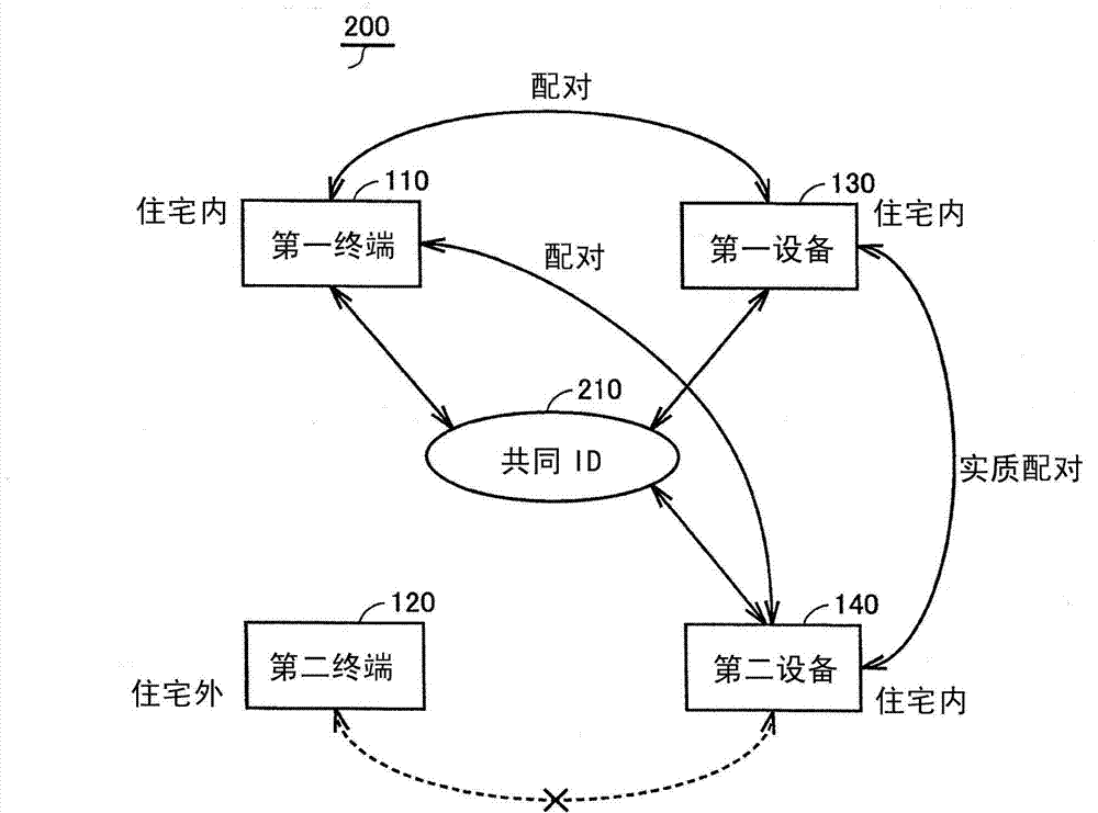
[0050] refer to figure 2 The network system 200 of the first embodiment will be described. figure 2 is a diagram conceptually showing the configuration of the network system 200 .

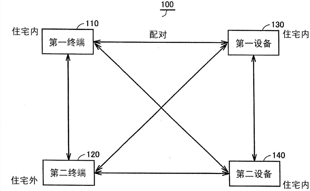
[0051] In a certain form, the network system 100 includes a first terminal 110 , a first device 130 , and a second device 140 . The first terminal 110, the first device 130, and the second device 140 are paired with each other via a common ID 210, respectively.

[0052] On the other hand, the second terminal 120 exists outside the house in which the network system 200 is constructed, for example, and the second terminal 120 is not paired with another device, for example, the second device 140 .

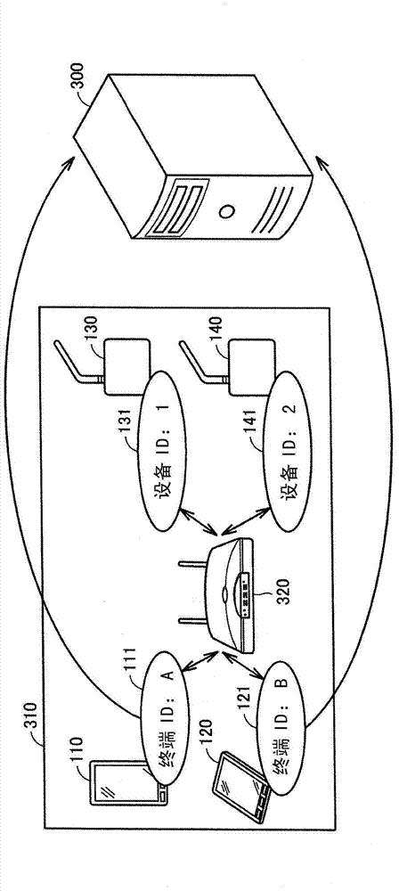
[0053] refer to image 3 The network system of this embodiment will be further described. image 3 It is a figure which shows the form of the network system 310.

[0054] The network system 310 is connected to the management server 300 . The network system 310 inc...

no. 2 approach

[0176] exist Figure 8 In the example shown, one common ID is illustrated as an ID for pairing, but a plurality of common IDs for pairing may be used in each same household. In this case, for example, each user may respectively have a common ID. In this way, it is possible to easily manage pairing in units of individuals.

[0177] The configuration other than the above configuration, that is, the configuration of the management server 300 and the communication terminal 400 used in the second embodiment, and the overall configuration of the network system are the same as those of the first embodiment, so detailed description thereof will not be repeated.

no. 3 approach

[0179] Instead of the processing shown in step S1130, data for displaying the registration screen may be held in communication terminal 400 in advance as an application program. According to such a configuration, the user of communication terminal 400 can input the common ID without establishing a communication session with management server 300 .

[0180] The configuration other than the above configuration, that is, the configuration of the management server 300 and the communication terminal 400 used in the third embodiment, and the overall configuration of the network system are the same as those of the first embodiment, and thus detailed description thereof will not be repeated.


PUM


Abstract

Provided is a wireless communication system that enhances the convenience of pairing. A hard disc (5) of a management server constituting a wireless communication system includes a database (810) having pairing information. The database (810) includes pairing information (820) and terminal device user information (830). The pairing information (820) includes terminal IDs (821) and device IDs (822). The terminal device user information (830) includes terminal IDs or device IDs (831) and common IDs (832). The terminal ID (111) of a first terminal, the terminal ID (121) of a second terminal, the device ID (131) of a first device and the device ID (141) of a second device are associated with one another by use of a common ID (840). The common ID (840) is a value specified in a column of common IDs (832) of the terminal device user information (830).

Description

technical field [0001] The present disclosure relates to pairing between wireless communication devices, and more particularly to setting or deleting of a pairing. Background technique [0002] A network in which devices with wireless communication functions are used with each other is gaining popularity. For wireless communication, it is necessary to perform pairing between devices in advance. [0003] Regarding pairing, for example, Japanese Patent Laid-Open Publication No. 2008-047022 (Patent Document 1) discloses an "Information Sharing System for Mobile Terminal Devices". According to the technology disclosed in Patent Document 1, "For the server device 200, the terminal registration unit 111 requests the registration of its own identification information, the shared information registration unit 113 requests the registration of its own user information, and the pairing registration unit 112 matches the registered identification information Between the other mobile te...

Claims


Application Information

Patent Timeline
IPC IPC(8): H04W8/26H04W4/08H04W84/10H04W4/21
CPCH04W4/08H04W8/26H04W84/10H04W4/21
Inventor 桥本俊和森下太一郎河田光司
Owner SHARP KK
Why Eureka
Try Eureka