
Device and method for determining positions of strip steel surface defect

A defect location and strip steel technology, applied in the field of strip defect detection equipment, can solve problems such as rising cost of automobile sheet products, full-length surface quality inspection of steel coils, and low production capacity of automobile sheet production lines, so as to avoid missed inspections and improve inspection The effect of ability

Inactive Publication Date: 2015-04-15
宝钢日铁汽车板有限公司
View PDF14 Cites 9 Cited by
  • Summary
  • Abstract
  • Description
  • Claims
  • Application Information

AI Technical Summary

Problems solved by technology

[0004] In the existing inspection mode, the inspection of the surface quality of the automobile sheet is mainly based on manual visual inspection. However, this manual method cannot perform real-time surface quality inspection on the entire length of the steel coil, and it is easy to miss some accidental or individual surface defects, resulting in low production efficiency of continuous units and high defect rate of end products
Especially when inspecting the quality of automobile sheet products with high surface quality, it is necessary to take post-process finishing quality inspection again based on manual visual inspection, which will cause low production capacity of the automobile sheet production line and increase the cost of automobile sheet products

Method used


Image

  • Device and method for determining positions of strip steel surface defect
  • Device and method for determining positions of strip steel surface defect
  • Device and method for determining positions of strip steel surface defect

Examples


Embodiment Construction

[0064] The device and method for determining the location of steel strip surface defects according to the present invention will be further explained and described below in conjunction with the accompanying drawings and specific embodiments, but the explanation and description do not constitute improper limitations on the technical solution of the present invention.

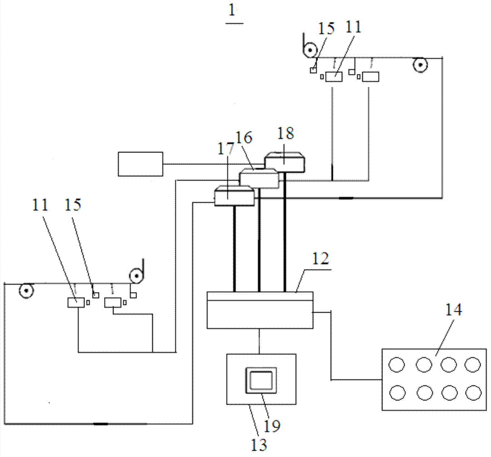
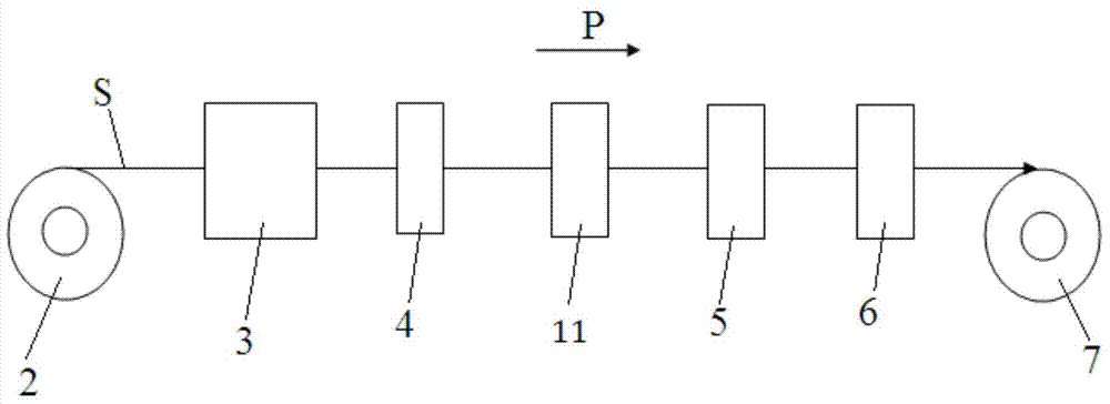
[0065] figure 1 shows the structure of the device for determining the position of the surface defect of the strip according to the present invention in one embodiment, and figure 2 It shows the state that the strip steel surface image acquisition device in the device is installed on the actual production line.

[0066] Such as figure 1 with figure 2As shown, the device 1 for determining the position of the strip surface defect in this embodiment includes a strip surface image acquisition device 11, a server 12, a workstation 13, an alarm device 14, an encoder 15, a first data receiver 16, a second A data rec...


PUM


Abstract

The invention discloses a device for determining positions of a strip steel surface defect, wherein the device comprises a strip steel surface image acquisition device; the strip steel surface image acquisition device is arranged on a strip steel production line, and is arranged at the upstream or the downstream of a loop along the strip steel traveling direction, and acquires image information of the upper surface and the lower surface of a strip steel; a server is connected with the strip steel surface image acquisition device through a first input port, and receives the image information transferred by the strip steel surface image acquisition device; the server has a second interface and receives strip steel production process data through the second interface; the server has a third interface and receives a signal for representation of an image defect length position; the server determines an actual position of the defect in the strip steel length direction and the position of the defect in the strip steel width direction according to the received image information, the strip steel production process data and the signal for representation of the image defect length position, and transfers the actual length position information and width position information of the defect on the strip steel out; a workstation displays the information transferred by the server.

Description

technical field [0001] The invention relates to a detection device, in particular to a strip defect detection device. Background technique [0002] In recent years, the rapid development experienced by China's automobile industry has also greatly promoted the rapid development of the automobile sheet production lines of iron and steel enterprises. Good surface quality is the prerequisite for the survival and development of the automobile sheets of various enterprises in the fierce market competition. Especially for high-quality automotive panels, automakers have stricter requirements on the surface quality of automotive panels. [0003] Since basically all automotive sheet production lines in the steel industry are continuous production lines, in order to realize special operations such as welding, quality inspection, and roll system replacement of the production line, the production line is generally planned regionally and configured in each area Loop sets are used to ensu...

Claims


Application Information

Patent Timeline
IPC IPC(8): G01N21/89
Inventor 何建锋蔡恒何春来
Owner 宝钢日铁汽车板有限公司
Learn More