
Pedestrian observation system, recording medium, and estimation of direction of travel

A technology of observation system and direction of travel, applied in the directions of measuring device, measuring distance, surveying and navigation, etc., can solve the problems of large amount of calculation, difficult to define, poor noise resistance, etc., and achieves high accuracy, suppresses the amount of calculation, and has good responsiveness. Effect

Inactive Publication Date: 2015-04-15
MEGACHIPS
View PDF12 Cites 12 Cited by
  • Summary
  • Abstract
  • Description
  • Claims
  • Application Information

AI Technical Summary

Problems solved by technology

[0011] However, the technique described in Patent Document 1 is a terminal device with a high degree of freedom of posture, but it assumes that the terminal device is kept in a stationary posture during walking motion, so there is a problem of lack of practicality.
In addition, since the data from the sensor is directly analyzed, there is a problem of poor noise immunity
Moreover, the acceleration data is kept successively, so there is also the problem of poor portability
[0012] In addition, in the technology described in Patent Document 2, statistical calculations are performed for a plurality of walking steps, so there is a problem of poor responsiveness.
[0013] In addition, the technologies described in Patent Documents 3, 4, and 6 are technologies related to frequency conversion, autocorrelation processing, etc., so there is a problem of a large amount of calculation
[0014] Furthermore, in the technology described in Patent Document 5, it is necessary to define the swing phase and the stance phase, but it is difficult to define them clearly, so there is a problem of increasing the number of erroneous measurements.

Method used


Image

  • Pedestrian observation system, recording medium, and estimation of direction of travel
  • Pedestrian observation system, recording medium, and estimation of direction of travel
  • Pedestrian observation system, recording medium, and estimation of direction of travel

Examples


no. 1 approach >

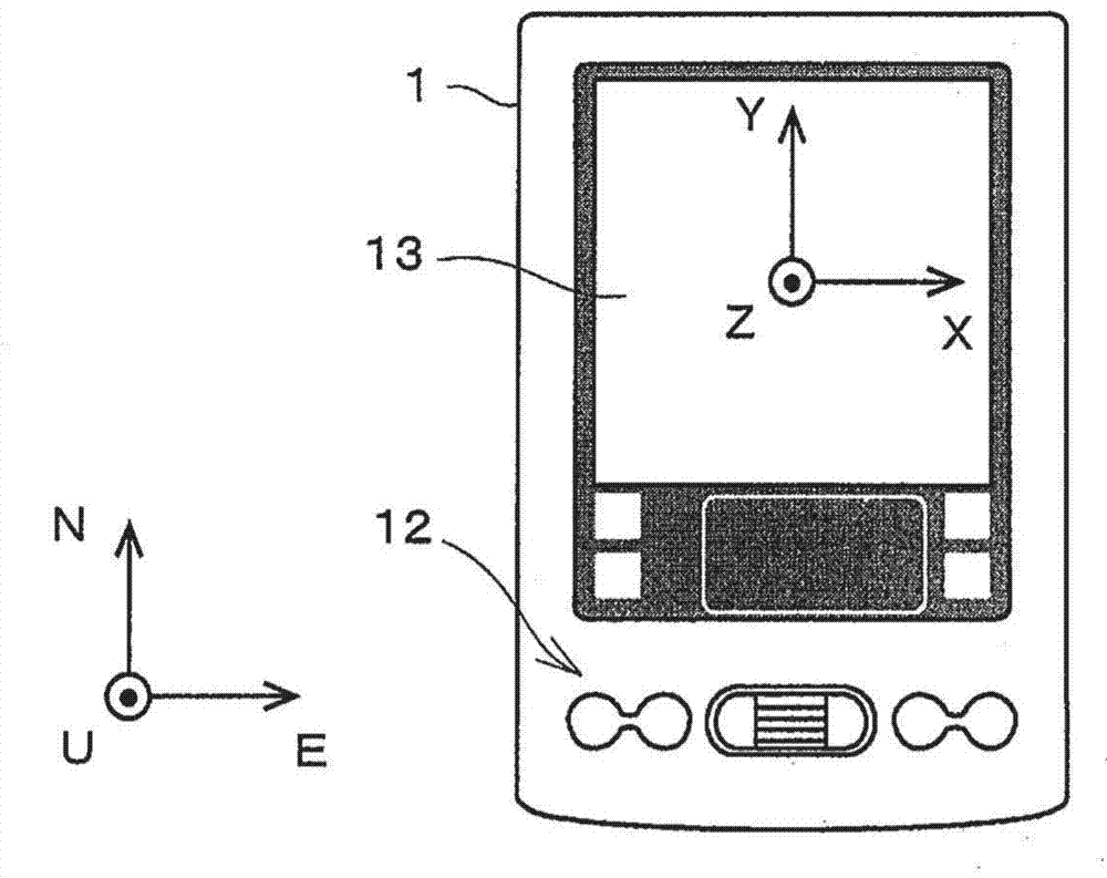
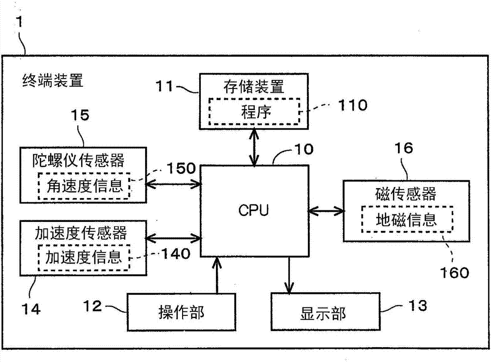
[0083] figure 1 It is a figure which shows the terminal device 1 of 1st Embodiment. figure 1 The shown ENU (East-North-Up: standing) coordinate system is a coordinate system independent of the terminal device 1, and is "a coordinate system independent of the motion of a pedestrian". In the ENU coordinate system, the eastward axis is defined as an E axis, the northward axis is defined as an N axis, and the vertically upward axis is defined as a U axis. in addition, figure 1 The shown XYZ coordinate system is a coordinate system defined on the terminal device 1 (terminal coordinate system), and in this embodiment, its origin is defined near the center of the screen of the display unit 13 . Among them, in this embodiment, the traveling direction and distance are calculated based on the relative positional relationship, so figure 1 The position of the origin shown is defined for convenience, and may also be defined at other positions.

[0084] exist figure 1 Among them, the X...

no. 2 approach >

[0222] In the first embodiment, the case where the terminal device 1 is not fixed to a pedestrian has been described. In this case, not only the acceleration sensor 14 but also the gyro sensor 15 and the magnetic sensor 16 need to be used to estimate the posture of the terminal device 1 . However, in the case of using an application such as PDR, it is conceivable that a terminal device for observing the walking behavior of the pedestrian is fixed to the body of the pedestrian. For example, attach the terminal to the waist of a walker, or put it in a breast pocket. If limited to such a usage form, the traveling direction can be estimated more easily than in the first embodiment.

[0223] Figure 11 It is a figure which shows the terminal device 2 of 2nd Embodiment. suppose Figure 11 The illustrated terminal device 2 measures the direction of travel while being put in the breast pocket of the walker. In addition, the terminal device 2 constitutes the pedestrian observation...

no. 3 approach >

[0234] In the second embodiment, an example in which the terminal device 2 (acceleration sensor 14 ) is substantially fixed to the body of a pedestrian has been described. However, under the situation of utilizing the PDR, the situation that the walker swings the arm back and forth while holding the portable device on the arm of the self occurs more frequently (hereinafter referred to as "arm swing state"). ). In addition, the "arm" mentioned here includes "hand", "finger" and the like. That is, "holding on the arm" includes a state of being held by the "hand", a state of being worn on the "finger" such as a ring-type device, and a state of being worn on the "wrist" with a strap or the like such as a watch-type device. state, or the state of being worn on the "forearm" in the form of a bracelet, etc.

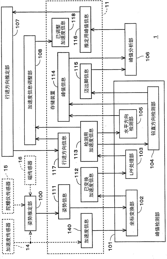
[0235] Figure 12 It is a diagram showing functional blocks included in the terminal device 3 according to the third embodiment together with data transfer. In the following...


PUM


Abstract

A pedestrian observation system includes a circuitry acquires an acceleration in accordance with a uniquely defined terminal coordinate system accompanying a pedestrian; obtains a power of an acceleration in a horizontal plane containing mutually perpendicular first and second directions based on acceleration components in the first and second directions, thereby acquiring an observation time of a maximum value of the power and acceleration components in the first and second directions at that time to acquire horizontal peak information; acquires times of observation of maximum and minimum values of a vertical acceleration component to acquire vertical peak information; chooses information on the maximum value of the power from the horizontal peak information based on the vertical peak information to acquire peak information for estimation; and acquires traveling direction information indicating a direction of travel of a pedestrian based on the peak information for estimation.

Description

technical field [0001] The present invention relates to a technique for estimating the traveling direction of pedestrians using a portable terminal device. Background technique [0002] Conventionally, there has been proposed a technique for specifying the traveling direction of a pedestrian in a portable terminal device having a high degree of freedom of posture. In particular, there is known an application program (PDR: Pedestrian Dead Reckoning) that allows a pedestrian to carry such a terminal device to observe the trajectory of the pedestrian. In such an application program, it is necessary to specify the direction of travel of the pedestrian. [0003] prior art literature [0004] patent documents [0005] Patent Document 1: Japanese Patent Laid-Open No. 2003-302419 [0006] Patent Document 2: Japanese Patent Laid-Open No. 2008-116315 [0007] Patent Document 3: Japanese Patent Application Publication No. 2006-104140 [0008] Patent Document 4: Japanese Patent Lai...

Claims


Application Information

Patent Timeline
Patent Type & Authority Applications(China)
IPC IPC(8): G01C21/12
CPCG01C22/006G01C21/10G01C21/12
Inventor 山冈卓纪夫
Owner MEGACHIPS
Learn More