Hydraulic oil cooler

A cooler and hydraulic oil technology, applied in the direction of transformer/inductor cooling, fluid pressure actuation device, fluid pressure actuation system components, etc., can solve the problems that power transformers affect the normal operation of power transformers, and achieve compact structure and low noise Low, good cooling performance

Inactive Publication Date: 2015-04-15
WUXI BOLIDA HEAT EXCHANGER
View PDF6 Cites 1 Cited by
  • Summary
  • Abstract
  • Description
  • Claims
  • Application Information

AI Technical Summary

Problems solved by technology

[0005] In view of the above existing problems, the present invention provides a hydraulic oil cooler to overcome the problem that the hydraulic oil cooler in the prior art cannot meet the hydraulic oil cooling requirements of the power transformer and thus affect the normal operation of the power transformer, so that a single hydraulic The oil cooler has larger capacity, better cooling performance, lower noise, compact structure, and easy installation, which is conducive to wide application in the power transformer industry

Method used


Image

  • Hydraulic oil cooler
  • Hydraulic oil cooler
  • Hydraulic oil cooler

Examples


Embodiment 1

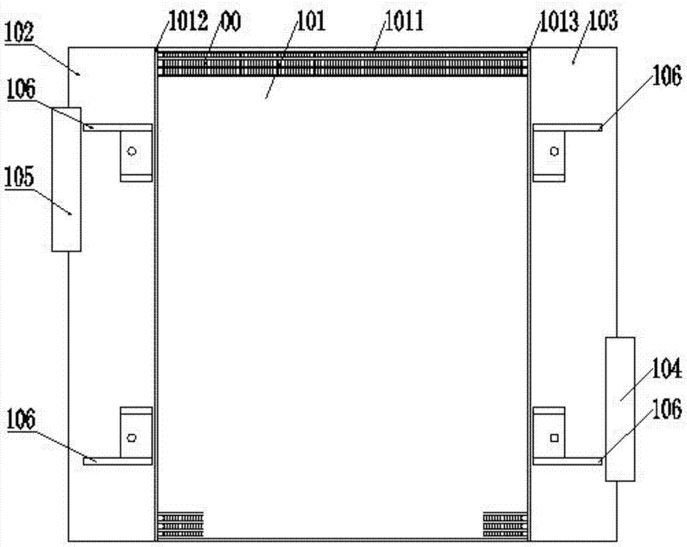
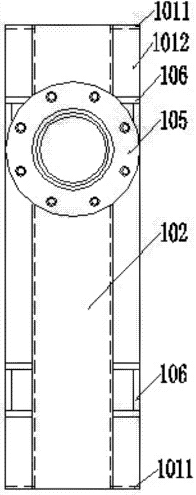
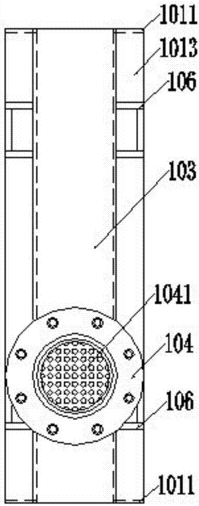
[0027] figure 1 It is the front view of the hydraulic oil cooler provided by Embodiment 1 of the present invention; figure 2 It is the left side view of the hydraulic oil cooler provided by Embodiment 1 of the present invention; image 3 It is the right side view of the hydraulic oil cooler provided by Embodiment 1 of the present invention; Figure 4 It is a top view of the hydraulic oil cooler provided by Embodiment 1 of the present invention; as shown in the figure, the hydraulic oil cooler provided by Embodiment 1 of the present invention includes: a cooling body 101 with a built-in cooling core 00, and the left side of the cooling body 101 The middle part is packaged with a left head 102, and the middle part of the right side of the cooling body 101 is packaged with a right head 103. The top, bottom, front and back of the cooling body 101 are all a thin plate 1011, and the left side of the cooling body 101 is front and rear. The parts on both sides are left strip-shaped...


PUM

PropertyMeasurementUnit
heightaaaaaaaaaa
distanceaaaaaaaaaa
thicknessaaaaaaaaaa

Abstract

The invention discloses a hydraulic oil cooler, and belongs to the field of structural design of the cooler. In the hydraulic oil cooler provided by the invention, an oil inlet flange and an oil outlet flange are integrally embedded into and molded with an end socket, so that hot oil can smoothly flow through a cooling body, the oil-side channel fin of a cooling core is designed to be a saw-tooth fin, the wind-side channel fin of the same is designed to be a straight porous fin, so that the hot oil in the cooling body is relatively long in heat exchange time and large in quantity, meanwhile external cold wind enters the cooling body uniformly, and thereby the problem that the normal operation of a power transformer is influenced due to that the hydraulic oil cooler in the prior art cannot meet the requirement on cooling the hydraulic oil of the power transformer, then the single hydraulic oil cooler is larger in capacity, better in cooling performance, lower in noise, compact in structure, easy to install, and beneficial to being widely applied to the industry of power transformers.

Description

technical field [0001] The invention relates to a cooler, in particular to a hydraulic oil cooler. Background technique [0002] Transformer is a device that uses the principle of electromagnetic induction to change AC voltage. According to its use, it can be divided into: distribution transformer, power transformer, fully sealed transformer, combined transformer, dry-type transformer, oil-immersed transformer, single-phase transformer, electric furnace transformer , rectifier transformer, etc. [0003] The hydraulic oil cooler is mainly used in the circuit of the hydraulic system of the transformer. When working, the high-temperature oil in the hydraulic system flows through the hydraulic cooler device, and performs efficient heat exchange with the forced-flowing cold air in the heat exchanger, so that the oil temperature drops. To the working temperature to ensure that the main engine can continue to operate normally, so that the work can be carried out smoothly. [0004...

Claims


Application Information

Patent Timeline
Patent Type & Authority Applications(China)
IPC IPC(8): F15B21/04H01F27/12
CPCF15B21/042H01F27/12
Inventor 管介善曹建国将健
Owner WUXI BOLIDA HEAT EXCHANGER
Why Eureka
Try Eureka