
Food cutting machine

A cutting machine and food technology, which is applied in the direction of grain processing, etc., can solve the problems of complex structure, large noise, and large number of parts, and achieve the effect of simple, reasonable and compact structure, reduced wear and noise, and smooth rotation of the winch drum

Active Publication Date: 2015-04-15
江门市江海区声辉电器有限公司
View PDF6 Cites 0 Cited by
  • Summary
  • Abstract
  • Description
  • Claims
  • Application Information

AI Technical Summary

Problems solved by technology

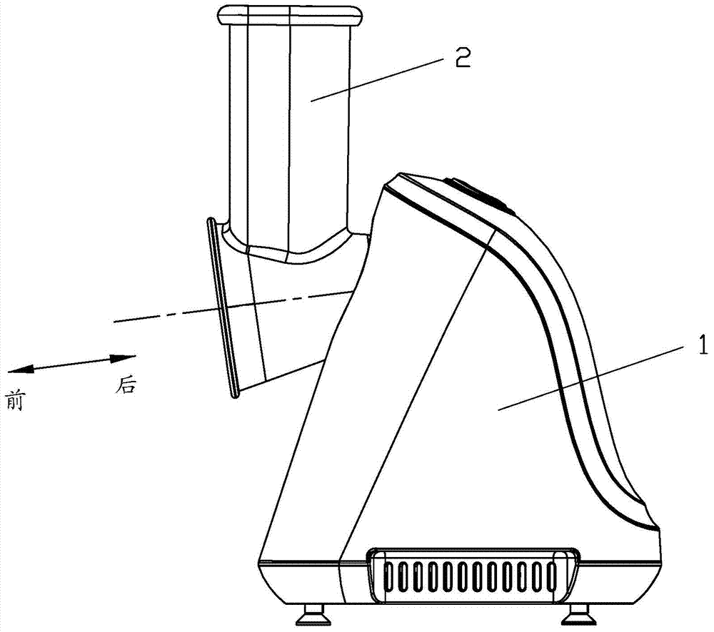
In traditional cooking, the processing of food materials is based on cutting and chopping with a kitchen knife by hand. This method is inefficient, the processed food materials are not uniform enough, and the labor load is large, which can no longer meet people's needs. Therefore, the current household appliances There is a food cutter in , specially designed for cutting or mincing food, see figure 1 As shown, its basic composition includes a fuselage 1, on which a feeding cylinder 2 is installed, and a winch is installed in the feed cylinder 2 (not visible when shielded), and the winch is connected to a power drive rod, Add the food from the feeding barrel, and the food enters the twisting barrel, which is attached with a sharp blade, and the twisting barrel rotates quickly under the drive of the power drive rod to chop the food
[0003] In order to facilitate the automatic sliding of the chopped food into the cup, the cavity of the feeding tube for accommodating the twisting cylinder and the twisting cylinder have a certain downward angle, which is convenient for the food to slide down automatically, but it will also make the twisting cylinder move forward Slipping, in order to solve this problem, in the traditional technology, an inner convex ring is provided at the front end of the twisting barrel in the cavity of the feeding barrel to prevent the twisting barrel from slipping, or various forms such as buckles are used to prevent the twisting barrel from slipping. The structure is either complicated, the number of parts is large, or the wear and tear is large, the noise is also large, and the disassembly and cleaning of the winch is inconvenient, which cannot meet people's needs well.

Method used


Image

  • Food cutting machine
  • Food cutting machine
  • Food cutting machine

Examples


Embodiment Construction

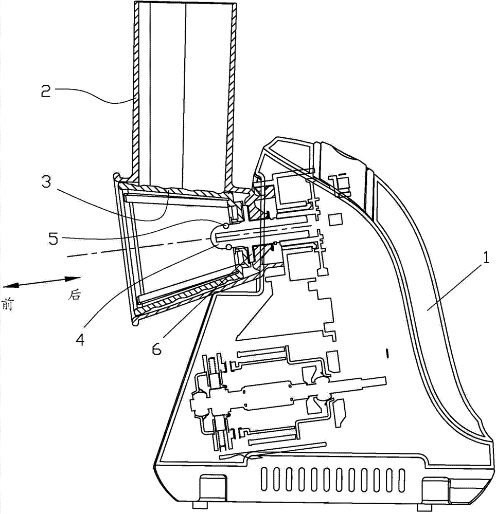
[0015] The present invention will be described in further detail below in conjunction with the accompanying drawings and embodiments. The front and rear in the following, unless otherwise specified, generally refer to the direction of the axis of the power drive rod 4, with the side where the food outlet of the twist drum 3 is located as the front, as shown by the arrow in the accompanying drawings.

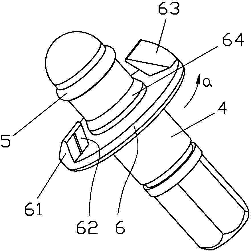
[0016] refer to Figure 1~Figure 5 , a kind of food cutting machine of the present invention, comprises fuselage 1, and described fuselage 1 is provided with feeding cylinder 2, and in feeding cylinder 2, is installed with twisted cylinder 3, and described twisted cylinder 3 is connected on the power drive bar 4, the twisted cylinder 3 is set on the power drive rod 4, and the front end of the power driven rod 4 passes through the sleeve hole 34 on the rear end surface of the twisted cylinder 3, and then is set with glue to prevent the twisted cylinder 3 from sliding forward. Rin...


PUM


Abstract

The invention discloses a food cutting machine, which comprises a body. The body is provided with a feeding cylinder, a wringing cylinder is installed in the feeding cylinder and is connected to a power drive rod, the wringing cylinder is sleeved on the power drive rod, the front end of the power drive rod passes through a casing hole at the rear end face of the wringing cylinder and is then sleeved with a rubber ring preventing the wringing cylinder from slipping forward, a limiting baffle plate is disposed on the power drive rod behind the wringing cylinder, and bumps are evenly distributed on the front end face of the limiting baffle plate circumferentially. The downstream sides of the bumps in the rotation direction are equipped with tilted gaps. The rear end face of the wringing cylinder has sloping panels fitted to the tilted gaps, when the power drive rod drives the wringing cylinder to rotate through the tilted gaps and the sloping panels, the tilted gaps cooperate with the sloping panels to provide a backward component force to the wringing cylinder so as to block the wringing cylinder from slipping forward. The food cutting machine provided by the invention has the characteristics of simple structure, good effect of avoiding wringing cylinder slip, small wear and low noise, and convenient assembly and disassembly and cleaning.

Description

technical field [0001] The invention relates to a food cutting machine. Background technique [0002] With the development of science and technology and the improvement of people's living standards, household appliances are becoming more and more popular. In traditional cooking, the processing of food materials is based on cutting and chopping with a kitchen knife by hand. This method is inefficient, the processed food materials are not uniform enough, and the labor load is large, which can no longer meet people's needs. Therefore, the current household appliances There is a food cutter in , specially designed for cutting or mincing food, see figure 1 As shown, its basic composition includes a fuselage 1, on which a feeding cylinder 2 is installed, and a winch is installed in the feed cylinder 2 (not visible when shielded), and the winch is connected to a power drive rod, Foodstuffs are added from the feeding barrel, and the ingredients enter into the twisting barrel, whic...

Claims


Application Information

Patent Timeline
Patent Type & Authority Applications(China)
IPC IPC(8): B02C18/06B02C18/16
CPCB02C18/065B02C18/16
Inventor 伍锦坤
Owner 江门市江海区声辉电器有限公司
Learn More