
On-board flywheel energy storage device

A technology of flywheel energy storage and flywheel, which is applied in the direction of electromechanical devices, control mechanical energy, electrical components, etc., can solve the problems of mechanical system complexity and increased manufacturing costs, and achieve the effects of improved energy utilization, convenient maintenance, and simple manufacturing

Active Publication Date: 2017-01-04
HARBIN ENG UNIV
View PDF11 Cites 0 Cited by
  • Summary
  • Abstract
  • Description
  • Claims
  • Application Information

AI Technical Summary

Problems solved by technology

In fact, the realization of high-efficiency flywheel kinetic energy recovery and energy storage needs to meet the conditions of low bearing loss and low wind resistance. Therefore, most of the automotive flywheel devices put into use use magnetic suspension support systems, and the flywheel is placed in a vacuum environment, resulting in the entire mechanical system. Significantly increased complexity and manufacturing costs

Method used


Image

  • On-board flywheel energy storage device
  • On-board flywheel energy storage device
  • On-board flywheel energy storage device

Examples


Embodiment Construction

[0019] The present invention is described in more detail below in conjunction with accompanying drawing example:

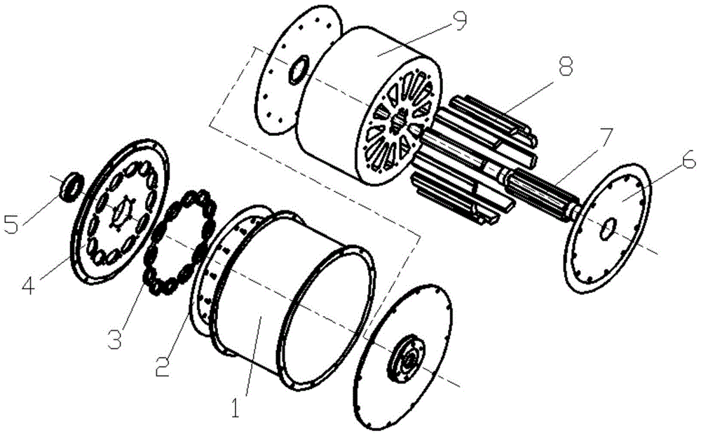
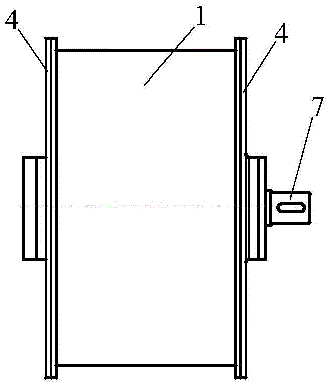
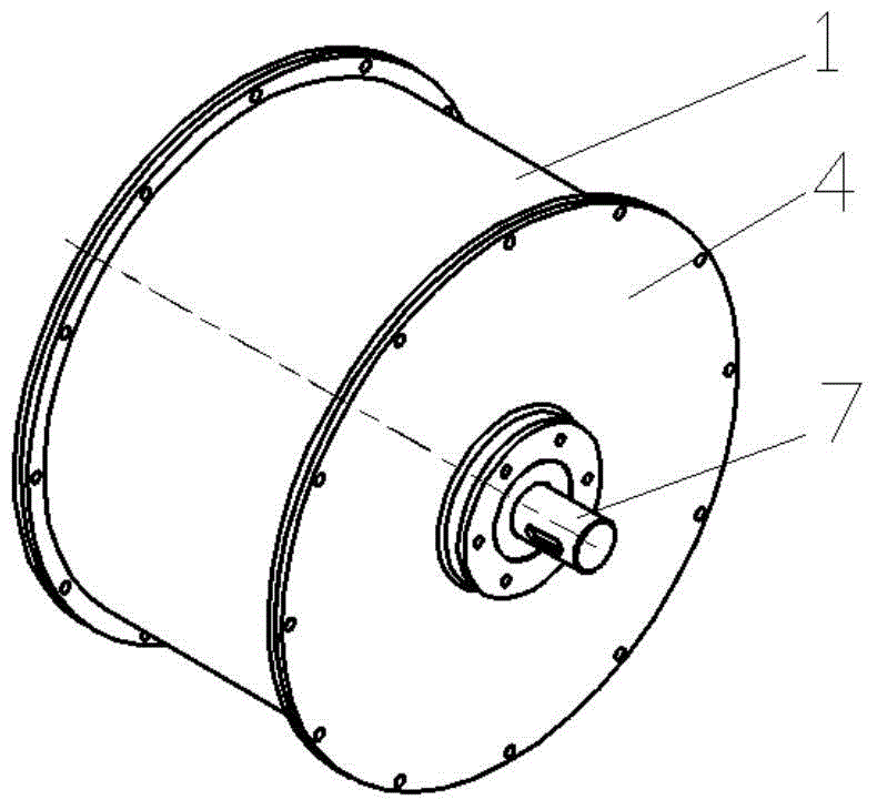
[0020] combine Figure 1-7 , the present invention mainly uses the short-term energy storage of the flywheel and recycles the braking energy in the form of mechanical energy. At the same time, it directly converts the braking energy converted into electrical energy and stored. The functions of the present invention are mainly realized by the following structures.

[0021] 1. Flywheel assembly (add power generation device)

[0022] The flywheel assembly consists of a flywheel rotor, a bar magnet, a flywheel shaft and a flywheel end cover. Bar magnets of different polarities are uniformly distributed in the gap of the flywheel rotor hub, and the bar magnets are positioned and installed through the upper top surface and the V-shaped face of the flywheel rotor hub gap. A spline shaft is installed in the middle of the flywheel rotor, and its function is to convert ...


PUM


Abstract

The invention aims to provide a vehicle-mounted flywheel energy storage device, which comprises a flywheel assembly and an outer shell assembly, wherein the flywheel assembly comprises a flywheel rotor and a spindle shaft; the flywheel rotor is provided with a through hole; the spline shaft is installed in the through hole; a long slot is arranged in the flywheel rotor; bar-shaped magnets are installed in the long slot; two ends of the flywheel rotor are both provided with flywheel end covers; the outer shell assembly comprises an outer shell, a coil winding and two bearing end covers, wherein the bearing end covers are independently installed on the outer sides of the two flywheel end covers; a non-metal baffle is independently installed between each bearing end cover and each flywheel end cover; the spline shaft passes through the two bearing end covers; the spline shaft is cooperated with the bearing end covers through a high-speed ball bearing; the outer shell is fixedly arranged between the two bearing end covers and is positioned on the outer part of the flywheel rotor; and an annular slot is independently arranged in each bearing end cover and is provided with the coil winding. A power generation device and a common high-speed bearing supporting system are introduced into the vehicle-mounted flywheel energy storage device, a vacuum structure is omitted, and the vehicle-mounted flywheel energy storage device is especially suitable for vehicles which need to be frequently started and stopped and also suitable for vehicles which need to go downhill.

Description

technical field [0001] The invention relates to an energy storage device, in particular to an automobile energy storage device. Background technique [0002] Currently popular hybrid vehicles in the market, as well as the hot research vehicle kinetic energy recovery system, are mainly realized by relying on chemical devices and flywheel devices for energy storage. Relatively speaking, hybrid electric vehicles and kinetic energy recovery systems using chemical devices as energy storage units are earlier and more widely used, and the technology is relatively mature. Transformation between each other, so the further improvement of efficiency is greatly restricted. From the perspective of energy conversion, the flywheel device has greater advantages, because the energy in the flywheel energy storage process always maintains the form of mechanical energy, which fundamentally ensures higher energy recovery efficiency. In fact, the realization of high-efficiency flywheel kinetic ...

Claims


Application Information

Patent Timeline
Patent Type & Authority Patents(China)
IPC IPC(8): H02K7/02
CPCY02E60/16
Inventor 史冬岩王青山陶家伟赵云科罗祥程梁谦
Owner HARBIN ENG UNIV
Learn More