
Construction method for taper-changeable composite fiber winding models

A composite fiber and construction method technology is applied in the field of construction of a three-dimensional model of a composite fiber variable taper winding product to achieve the effects of improving design efficiency, simplifying the design process, and being supported by good data and logical relationships.

Inactive Publication Date: 2015-04-08
XIAN TECHNOLOGICAL UNIV
View PDF4 Cites 9 Cited by
  • Summary
  • Abstract
  • Description
  • Claims
  • Application Information

AI Technical Summary

Problems solved by technology

[0004] The purpose of the embodiment of the present invention is to provide a method for constructing a composite fiber variable taper winding model, which aims to solve the problem of creating a cylindrical helical line equation combined with three-dimensional graphics transformation due to the extremely large winding length of the composite fiber winding product. Problems with 3D Variable Taper Winding Models Available for Numerical Analysis

Method used

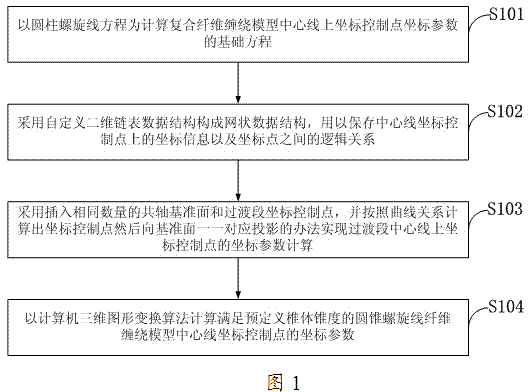
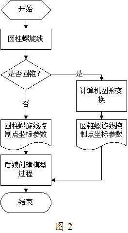

Image

  • Construction method for taper-changeable composite fiber winding models
  • Construction method for taper-changeable composite fiber winding models
  • Construction method for taper-changeable composite fiber winding models

Examples


Embodiment 1

[0048] Embodiment 1: a method for building a composite fiber winding product model based on cylindrical helical curve and computer three-dimensional graphics transformation, comprising the following steps:

[0049] Step 1: Determine the diameter of the cylinder helix equation and the axial length of the helix according to the design requirements of the filament winding product, and then calculate the coordinate parameters of all coordinate control points on the center line of the filament winding model from the cylinder helix equation;

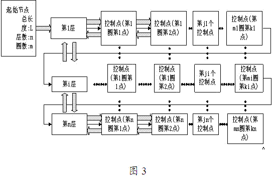
[0050] Step 2: Create a image 3 The mesh data set of the fiber centerline coordinate control points shown, wherein the coordinate parameters of all the centerline coordinate control points calculated by the cylindrical helix and the logical relationship between the coordinate control points are stored;

[0051] Step 3: For the adjustment of the coordinate control points of the jump / cross-circle part, several coordinate control points and the ...

Embodiment 2

[0053] Embodiment 2: a kind of method of constructing fiber winding model based on cylindrical helical curve and computer three-dimensional graphics transformation:

[0054] Step 1: Determine the spacing of the cylinder helix equation and the number of turns in the first layer according to the design requirements of the filament winding product, and then calculate the coordinate values ​​of all coordinate control points of the center line of the filament winding model from the cylinder helix equation;

[0055] Step 2: Create a image 3 The mesh data set of the fiber centerline coordinate control points shown, wherein the coordinate parameters of all the centerline coordinate control points calculated by the cylindrical helix and the logical relationship between the coordinate control points are stored;

[0056] Step 3: For the adjustment of the coordinate control points of the jump / cross-circle part, several coordinate control points and the same number of coaxial reference pl...

Embodiment 3

[0058] Embodiment 3: a kind of method based on cylindrical helical curve and computer three-dimensional graphics transformation to construct filament winding model:

[0059] Step 1: Determine the diameter of the cylindrical helix equation, the axial length of the helix and the helix spacing according to the design requirements of the filament winding product, and then calculate the coordinate values ​​of all coordinate control points of the centerline of the fiber winding model from the helix equation of the cylinder ;

[0060] Step 2: Create a image 3 The mesh data set of the fiber centerline coordinate control points shown, wherein the coordinate parameters of all the centerline coordinate control points calculated by the cylindrical helix and the logical relationship between the coordinate control points are stored;

[0061] Step 3: For the correction of the coordinate control points of the jump / cross-circle part, several coordinate control points and the same number of c...


PUM


Abstract

The invention discloses a construction method for taper-changeable composite fiber winding models. According to the construction method, coordinates of positioning control points on winding fibers in a three-dimensional space are calculated according to a normalized curvilinear equation, and modeling of composite fiber winding products is realized by combining a three-dimensional modeling software solid feature operation method; the problems that mutual fiber interference among three-dimensional solid models of spring layer / striding circle positions during fiber winding simulation is caused and the control points need to be corrected to avoid the interference are solved; the construction method can construct the fiber winding models with any filament winding lengths, and the models have high similarity to actual fiber winding products; the fiber winding models have wide range of adaptability to taper of winding mandrel bodies and high dimensional accuracy. By the construction method, the fiber winding products as required can be automatically generated according to parameters inputted by users, and design efficiency is improved; fiber interference and intersection conditions, including spring layer intersection and circle change intersection, during winding of fibrous composite products can be simulated to the greatest extent; the three-dimensional models of the fiber winding products have high similarity to the actual products in terms of boundary dimension.

Description

technical field [0001] The invention belongs to the technical field of computer graphics and three-dimensional modeling, in particular to a method for constructing a three-dimensional model of a composite fiber variable taper winding product. Background technique [0002] Composite fiber winding molding is to impregnate the continuous fiber with resin glue, under the action of fixed tension, wind it on the mandrel according to the predetermined relative motion law, and form a fiber winding product with a specific shape after curing and molding. Common composite filament winding products are generally cylindrical or conical with an axisymmetric shape. The common manufacturing method is to wind the fiber on the mandrel according to the trajectory of the helix. The law of motion is that the mandrel rotates at a constant speed around its central axis, and the winding head moves back and forth along the axis of the mandrel at a specific speed, thereby realizing spiral winding on...

Claims


Application Information

Patent Timeline
Patent Type & Authority Applications(China)
IPC IPC(8): G06F17/50G06T17/00
Inventor 方舟曹岩姚慧白瑀杜江
Owner XIAN TECHNOLOGICAL UNIV
Learn More