Compression splicing equipment and method

A technology for crimping equipment and equipment, applied in nonlinear optics, instruments, optics, etc., can solve problems such as low repair efficiency, and achieve the effect of high-voltage connection efficiency and less structure

Active Publication Date: 2015-04-08
BOE TECH GRP CO LTD +1
View PDF6 Cites 3 Cited by
  • Summary
  • Abstract
  • Description
  • Claims
  • Application Information

AI Technical Summary

Problems solved by technology

The crimping equipment in the prior art generally includes one indenter, which can only crimp COF / FPC at one position at a time, and the repair efficiency is very low

Method used


Image

  • Compression splicing equipment and method
  • Compression splicing equipment and method

Examples


Embodiment 1

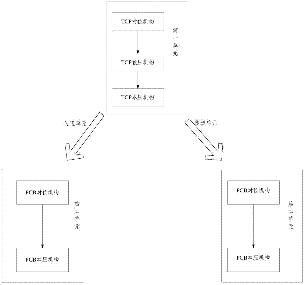
[0035] Embodiment 1 of the present invention provides a crimping device, which can be used to crimp a flexible connection circuit board to a panel and a circuit board during maintenance, such as figure 1 Shown is a schematic structural diagram of the device, including: a first unit, two left and right second units, and a transmission unit (transmission unit not shown) for connecting the second unit and the first unit, wherein the first unit It includes a panel side preloading mechanism (corresponding to the TCP preloading in the figure), and the panel side preloading mechanism includes a pressure head (not shown in the figure), and each second unit includes a local pressure mechanism, each of which The pressing mechanism includes a plurality of pressing heads (not shown in the figure), and the position of each of the pressing heads included in each pressing mechanism can be adjusted independently.

[0036] In the embodiment of the present invention, on the one hand, the crimpi...

Embodiment 2

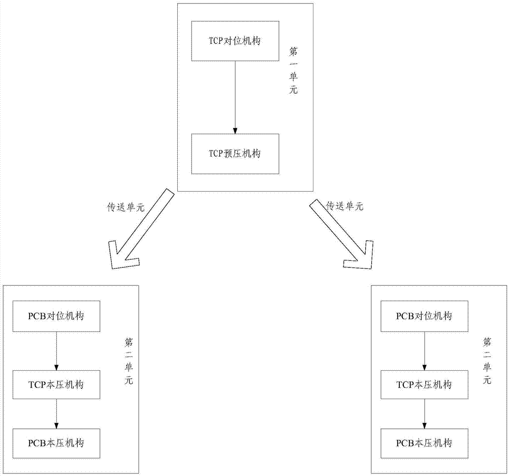
[0055] Such as figure 2 As shown, it is a schematic structural diagram of a crimping equipment provided in Embodiment 2 of the present invention, and figure 1 The difference is that in the crimping equipment provided in the embodiment of the present invention, the first unit includes a panel-side alignment mechanism (corresponding to the TCP alignment in the figure), a panel-side pre-pressing mechanism (corresponding to TCP preloading in the figure); each second unit includes a panel-side pressure mechanism (corresponding to the TCP pressure in the figure), a printed circuit side alignment mechanism (corresponding to the PCB alignment in the figure) and a The printed circuit side pressure mechanism (corresponding to the PCB pressure mechanism in the figure); the specific structure of the panel side pressure mechanism and the panel side preload mechanism here can be consistent with the corresponding structure of the first embodiment.

[0056] In a specific application, if the...


PUM


Abstract

The invention discloses compression splicing equipment and method. The compression splicing equipment comprises a first unit and at least two second units, the first unit comprises a panel side pre-compressing mechanism, and the panel side pre-compressing mechanism comprises a compression head; each second unit comprises at least one compressing mechanism, each compressing mechanism comprises a plurality of compression heads, and the position of each compression head of each compressing mechanism can be adjusted independently. On the one hand, a plurality of flexible connecting circuit boards can be performed with compression splicing in one time through regulating each compression head to the corresponding position, and on the other hand, because the compression splicing equipment comprises the pre-compressing mechanism, the flexible connecting circuit boards can be pre-fixed on the panel before compressing the flexible connecting circuit boards. Because the pre-compressing efficiency is obviously higher than the compressing efficiency, the pre-compressing mechanism comprising one compression head rarely influences the overall compression splicing efficiency. The compression splicing equipment is simple in structure and high in compression splicing efficiency.

Description

technical field [0001] The invention relates to the field of display technology, in particular to a crimping device and method. Background technique [0002] In the production process of liquid crystal displays, it is necessary to connect the panel with multiple corresponding PCBs (Printed Circuit Board, printed circuit board) ) are connected, and generally the two sides of the COF / FPC are correspondingly crimped to the panel and PCB through the crimping process. The defect rate of the crimping process in the prior art is relatively high, and the crimping of some COF / FPCs is often unqualified, which needs to be repaired through a subsequent repair process. When repairing, peel off the unqualified COF / FPC, and then use crimping equipment to crimp the COF / FPC again. The crimping equipment in the prior art generally includes one indenter, which can only crimp COF / FPC at one position at a time, and the repair efficiency is very low. Contents of the invention [0003] The pu...

Claims


Application Information

Patent Timeline
Patent Type & Authority Applications(China)
IPC IPC(8): G02F1/13
CPCG02F1/1309G02F2201/506
Inventor 肖晗王鹏谷晓飞李建超
Owner BOE TECH GRP CO LTD
Why Eureka
Try Eureka