A microfluidic unit for improved detection specificity
A microfluidic unit and specific technology, applied in the field of sensors, can solve problems such as the inability to realize single or small cells and small microfluidics, and achieve the effect of improving detection efficiency and quality, improving sensitivity and specificity, and reducing bacterial culture links.
- Summary
- Abstract
- Description
- Claims
- Application Information
AI Technical Summary
Problems solved by technology
Method used
Image
Examples
Embodiment 1
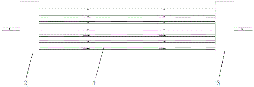
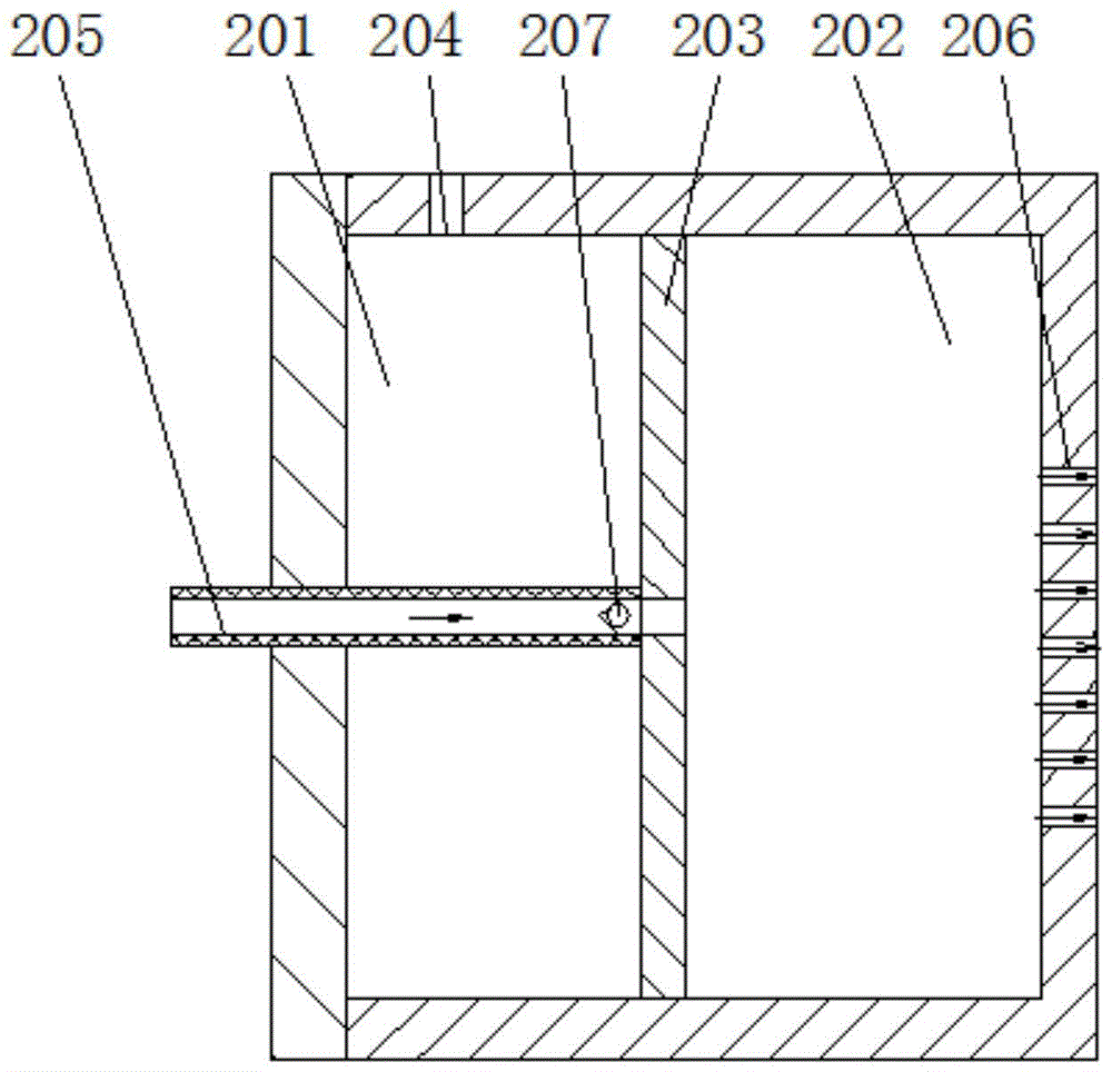
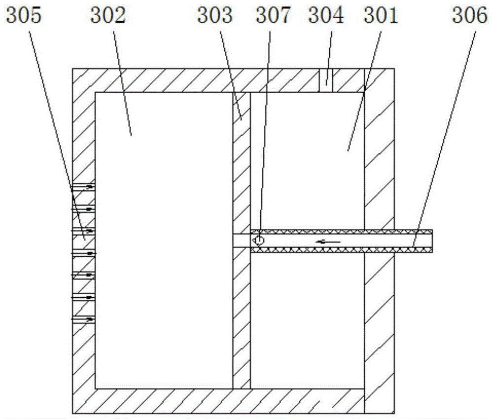
[0026] Such as Figure 1 to Figure 3 As shown, in this embodiment, a microfluidic unit for improving detection specificity includes at least one microfluidic body 1 in a tubular structure, and a positive pressure generating device 2 is provided at the cell inlet end of the microfluidic body, and the microfluidic body A negative pressure generator 3 is provided at the cell outlet. The positive pressure generating device generates positive pressure, and the negative pressure generating device generates negative pressure. Under the joint action of positive and negative pressure, cells in the cell solution are pushed into the microfluidic body 1 to realize detection.
[0027] In this implementation, a microfluidic unit with a pipe diameter of 4-6 μm, preferably 5 μm, is used to increase positive pressure and negative pressure generating devices at both ends of the microfluidic body, so that sufficient negative pressure can be generated in the microfluidic body to allow the Only a...
Embodiment 2
[0034] Such as Figure 4 As shown, the difference between embodiment 2 and embodiment 1 is that the microfluidic body 1 is set as a Y-shaped structure, that is, the microfluidic body is combined into a unified channel before the negative pressure generating device 3 is connected, so that multiple microfluidic bodies 1 The centralized processing of the pipes forms a negative pressure structure, and the cell solution is more likely to enter the microfluidic body 1, and the effect is better. Other structures are the same as in Embodiment 1, and will not be described here again.
Embodiment 3
[0036] Such as Figure 5 For Example 3, the difference from Example 1 is that the microfluidic body 1 is set in a U-shaped structure, which can increase the length of the microfluidic body, and it is easier to disperse a certain number of cells to be tested, which is conducive to the entry of the cell solution Microfluidic body 1, the effect is better. Other structures are the same as in Embodiment 1, and will not be described here again.
PUM
| Property | Measurement | Unit |
|---|---|---|
| diameter | aaaaa | aaaaa |
Abstract
Description
Claims
Application Information
 - R&D Engineer
- R&D Manager
- IP Professional
- Industry Leading Data Capabilities
- Powerful AI technology
- Patent DNA Extraction
Browse by: Latest US Patents, China's latest patents, Technical Efficacy Thesaurus, Application Domain, Technology Topic, Popular Technical Reports.
© 2024 PatSnap. All rights reserved.Legal|Privacy policy|Modern Slavery Act Transparency Statement|Sitemap|About US| Contact US: help@patsnap.com


