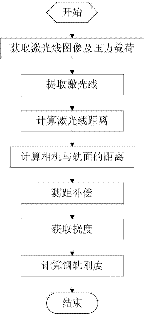
Rail rigidity measuring method based on machine vision
A technology of machine vision and measurement methods, applied in the direction of measuring devices, instruments, etc., can solve the problem of different loads twice
- Summary
- Abstract
- Description
- Claims
- Application Information
AI Technical Summary
Problems solved by technology
Method used
Image
Examples
Embodiment Construction
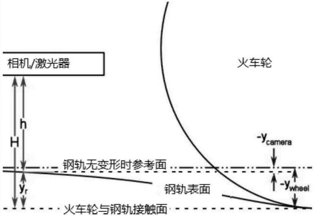
[0027] The measurement system involved in this specific embodiment includes two one-line lasers and a camera, and the camera is used as a machine vision sensor. As shown in the figure, the camera and the measurement carrier are fixed by structural members, so that the camera is installed directly above the rail surface, and the camera moves synchronously with the wheel in the direction perpendicular to the driving direction. Two in-line lasers are installed on the same level as the vision sensor. The two in-line lasers cross and emit in-line lasers respectively, and the camera captures the imaging of the two in-line lasers on the rail above the track, which is figure 2 Laser line shown. Among them, the laser line on the left is the imaging of the line laser on the right side of the camera, and the laser line on the right is the imaging of the line laser on the left side of the camera. The shortest distance between the two laser lines is d.
[0028] like image 3 As shown ...
PUM
 Abstract
Description
Claims
Application Information
 - R&D Engineer
- R&D Manager
- IP Professional
- Industry Leading Data Capabilities
- Powerful AI technology
- Patent DNA Extraction
Browse by: Latest US Patents, China's latest patents, Technical Efficacy Thesaurus, Application Domain, Technology Topic, Popular Technical Reports.
© 2024 PatSnap. All rights reserved.Legal|Privacy policy|Modern Slavery Act Transparency Statement|Sitemap|About US| Contact US: help@patsnap.com


