An impeller degreasing fixture

A degreasing and fixture technology, which is used in the parts of pumping devices for elastic fluids, non-variable volume pumps, centrifuges, etc., can solve problems such as customer unacceptance, affecting product appearance, and increasing the amount of anti-rust oil. , to achieve the effect of simple and novel structure, improving the quality and efficiency of deoiling, and high deoiling efficiency

Active Publication Date: 2016-12-07
CHONGQING FEILONG JANSANT AUTO PARTS
View PDF7 Cites 0 Cited by
  • Summary
  • Abstract
  • Description
  • Claims
  • Application Information

AI Technical Summary

Problems solved by technology

This impeller degreasing fixture is mainly for products coated with anti-rust oil on the surface. After the impeller is soaked in anti-rust oil, thick anti-rust oil will accumulate on the surface and root, which will affect the appearance of the product, and the customer does not accept it. ;Secondly, the amount of anti-rust oil will increase

Method used


Image

  • An impeller degreasing fixture

Examples


Embodiment Construction

[0013] The present invention will be further described below in conjunction with the embodiments and accompanying drawings.

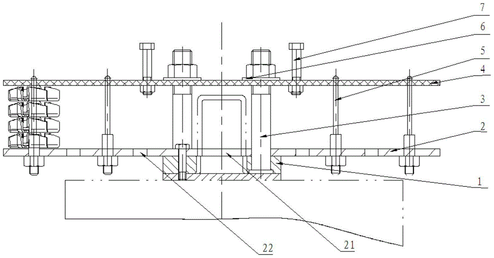
[0014] like figure 1 The illustrated impeller deoiling fixture includes a base plate 2 and a cover plate 4 located above the base plate 2, a positioning plate 1 is connected below the base plate 2, and a guide hole 21 is provided in the center of the base plate 2, and a guide hole 21 is provided in the guide hole. The base plate 2 around 21 is densely covered with oil leakage and weight-reducing holes 22, the base plate 2 and the cover plate 4 are connected by positioning columns 3, and the positioning columns 3 are two, respectively located on both sides of the guide hole 21 , the upper end of the positioning column 3 protrudes from the cover plate 4, and the extended end is connected with a nut through a washer 6, and several screw rods 5 are connected between the base plate 2 and the cover plate 4, that is, on the base plate 2 Two turns of the screw...


PUM


Abstract

The invention discloses an impeller oil removing fixture which comprises a bottom plate and a cover plate. The cover plate is positioned above the bottom plate and is connected with the bottom plate by positioning columns, and a plurality of screws are arranged between the bottom plate and the cover plate in a connected manner. The impeller oil removing fixture with the structure has the advantages that the fixture is fixed onto a rotary mechanism when used, the cover plate is lifted up, impellers with oil required to be removed sleeve the screws which are arranged on the bottom plate, the cover plate is arranged in a covering manner after the impellers are arranged, a motor can be started, the fixture can rotate, accordingly, the oil on the impellers can be thrown out under the effect of centrifugal force, and oil removing effects can be realized.

Description

technical field [0001] The invention belongs to the technical field of automobile water pumps, and in particular relates to an impeller deoiling fixture. Background technique [0002] In the cylinder block of the car engine, there are many water channels for cooling water circulation, which are connected with the radiator placed in the front of the car through water pipes to form a large water circulation system. A water pump is installed at the upper water outlet of the engine. Pump out the hot water in the water channel of the engine block and pump the cold water in. There is also a thermostat next to the water pump. When the car is just started (cold car), it is not turned on, so that the cooling water does not pass through the water tank, but only circulates in the engine (commonly known as small circulation). When the temperature of the engine reaches 95 degrees or more When it is turned on, the hot water in the engine is pumped into the water tank, and the cold wind b...

Claims


Application Information

Patent Timeline
Patent Type & Authority Patents(China)
IPC IPC(8): F04D29/00
CPCB04B5/12
Inventor 江万里陈先蓉
Owner CHONGQING FEILONG JANSANT AUTO PARTS
Why Eureka
Try Eureka