
a laying machine

A technology of a laying machine and a laying device, applied in the direction of construction and building structure, can solve the problems of long decoration period, fall of construction personnel, hidden safety hazards, etc., and achieve the effect of reasonable structural design, high degree of automation, and improved efficiency.

Active Publication Date: 2017-08-01
WUHU YINXING AUTO PARTS
View PDF7 Cites 0 Cited by
  • Summary
  • Abstract
  • Description
  • Claims
  • Application Information

AI Technical Summary

Problems solved by technology

[0002] The existing interior decoration adopts the method of artificially laying the ceiling, that is, the ceiling fixed frame is erected, and evenly distributed rectangular grooves are separated on the ceiling fixed frame. The position of the rectangular groove is used for laying the ceiling, usually for manual ladder The method lays the ceiling in the corresponding rectangular groove. After each piece of ceiling is laid, the ladder needs to be moved to install the ceiling at the next position. This method is inefficient, and the operator needs to climb the ladder repeatedly. Potential safety hazards, easy to cause construction personnel to fall, make the decoration cycle longer, and increase the cost of decoration

Method used


Image

  • a laying machine
  • a laying machine
  • a laying machine

Examples


Embodiment Construction

[0015] In order to make the technical means, creative features, goals and effects achieved by the present invention easy to understand, the present invention will be further elaborated below.

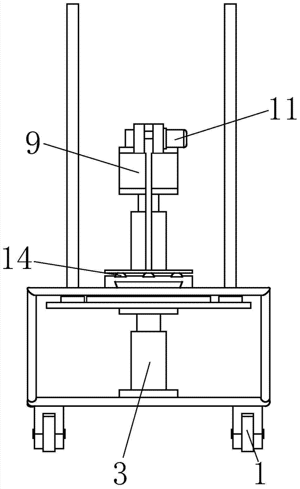
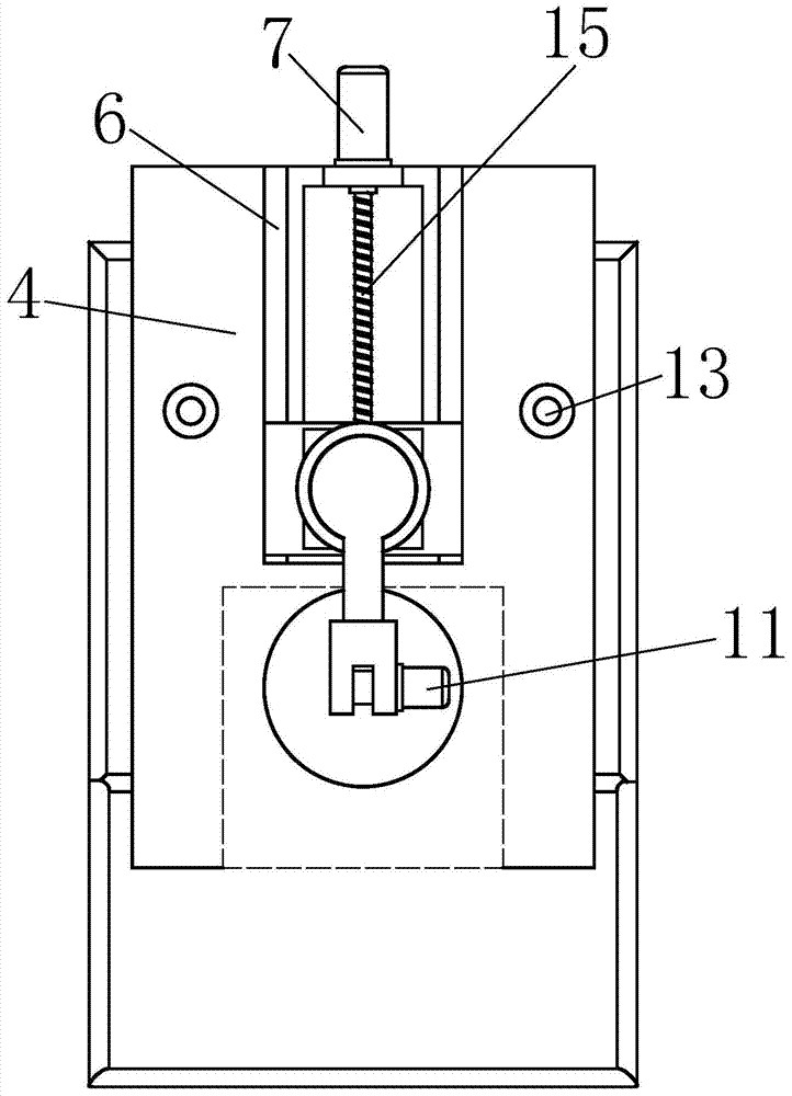
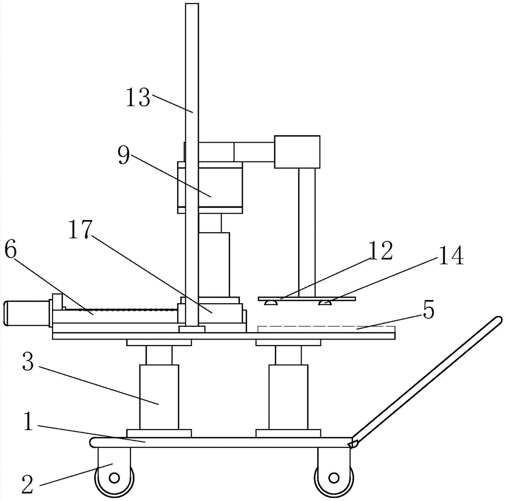
[0016] Such as Figure 1 to Figure 4 As shown, a laying machine includes a machine body 1, a walking wheel 2, a reference alignment device and a feeding and laying device, the walking wheel 2 is fixed on the bottom of the body 1, and the front part of the body 1 is provided with a handle 1a, The reference alignment device is installed on the upper end surface of the machine body 1, and the material feeding and laying device is installed in the middle of the upper end of the reference alignment device. When laying the ceiling 5, the operator first stacks the ceiling 5 on the datum alignment device, then pushes the handle 1a to move the body 1 to the right below the rectangular slot of the ceiling 5 fixing frame, and then starts the datum alignment device to perform datum Correction, aft...


PUM


Abstract

The invention relates to a laying machine. The laying machine comprises a machine body, travelling wheels, a reference alignment device and a loading laying device, wherein the travelling wheels are fixed at the bottom of the machine body, a handle is arranged at the front part of the machine body, the reference alignment device is mounted on the upper end surface of the machine body, and the loading laying device is mounted at the middle part of the upper end of the reference alignment device. The laying machine disclosed by the invention has the advantages of being reasonable in structural design, high in automation degree, convenient to operate and control, and the like, can realize automatic laying of ceilings, replaces a traditional manner that builders climb a ladder for laying, improves the laying efficiency and has the protective effect on the builders.

Description

technical field [0001] The invention relates to special equipment for decoration, in particular to a laying machine. Background technique [0002] The existing interior decoration adopts the method of artificially laying the ceiling, that is, the ceiling fixed frame is erected, and evenly distributed rectangular grooves are separated on the ceiling fixed frame. The position of the rectangular groove is used for laying the ceiling, usually for manual ladder The method lays the ceiling in the corresponding rectangular groove. After each piece of ceiling is laid, the ladder needs to be moved to install the ceiling at the next position. This method is inefficient, and the operator needs to climb the ladder repeatedly. Potential safety hazards can easily cause construction personnel to fall, which makes the decoration cycle longer and increases the cost of decoration. Contents of the invention [0003] Aiming at the above-mentioned technologies, the present invention proposes ...

Claims


Application Information

Patent Timeline
Patent Type & Authority Patents(China)
IPC IPC(8): E04F21/18
Inventor 曹志刚
Owner WUHU YINXING AUTO PARTS
Learn More