
Weight clamping mechanical gripper for metrological verification work

A technology of metrology verification and manipulator claws, which is applied in the direction of manipulators, chucks, manufacturing tools, etc., can solve the problems of inability to accurately ensure the quality of verification work, damage to weighing equipment, and rough structures, so as to achieve high verification work efficiency and increase grabbing. The effect of strong adaptability and overload capacity

Inactive Publication Date: 2015-04-08
ZHENJIANG MEASUREMENT VERIFICATION TEST CENT +1
View PDF7 Cites 26 Cited by
  • Summary
  • Abstract
  • Description
  • Claims
  • Application Information

AI Technical Summary

Problems solved by technology

In the existing weight verification technology, the loading and unloading of weights is usually carried out by manual positioning and manual handling, which requires a lot of physical labor for the verification personnel, and the efficiency is low. Moreover, due to human misoperation, it may cause damage to the weighing equipment.
Therefore, manual positioning and manual handling of weights cannot accurately guarantee the quality of the verification work
[0003] Due to the requirements of operating precision and structural rigidity, traditional industrial robots or clamping manipulators are often bulky and clumsy in structure

Method used


Image

  • Weight clamping mechanical gripper for metrological verification work
  • Weight clamping mechanical gripper for metrological verification work
  • Weight clamping mechanical gripper for metrological verification work

Examples


Embodiment Construction

[0034] The present invention will be further described below in conjunction with the accompanying drawings and specific embodiments, but the protection scope of the present invention is not limited thereto.

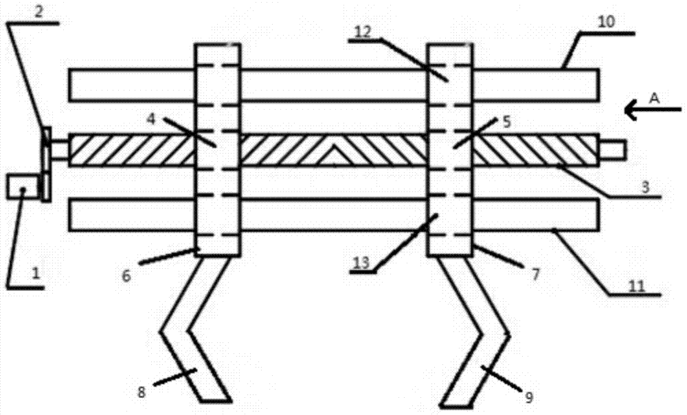
[0035] Such as figure 1 and figure 2 As shown, a weight clamping manipulator used for metrological verification work includes an AC servo motor 1, a reduction gear 2, a double-rotation screw 3, a first screw nut 4, a second screw nut 5, a second screw nut A connecting platen 6, a second connecting platen 7, a first clamp 8, a second clamp 9, a first linear guide rail 10, a second linear guide rail 11, a first linear bearing 12 and a second linear bearing 13; The AC servo motor 1 is connected to the reduction gear 2, and the reduction gear 2 is connected to the double-rotation screw 3 through a key; a part of the double-rotation screw 3 is connected to the first screw nut 4, and the other part is connected to the second screw nut 4. Lead screw nut 5 converts rotary moti...


PUM

PropertyMeasurementUnit
Lengthaaaaaaaaaa

Abstract

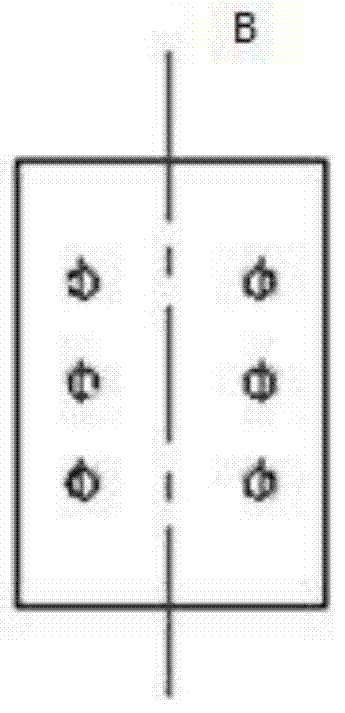
The invention provides a weight clamping mechanical gripper for metrological verification work. The weight clamping mechanical gripper comprises an alternating current servo motor, a speed reduction gear, a double-rotation direction screw rod, screw rod nuts, connecting pressure plates, a first clamp, a second clamp, linear guide tracks and linear bearings, wherein the alternating current servo motor is connected with the double-rotation direction screw rod through the speed reduction gear, two screw rod nuts are matched and connected onto the double-rotation direction screw rod, the two screw rod nuts are nested in middle holes in the first connecting pressure plate and the second connecting pressure plate, and the side surfaces B of the first connecting pressure plate and the second connecting pressure plate are respectively connected with the left angle bracket-shaped first clamp and the right angle bracket-shaped second clamp; the two linear guide tracks are arranged on two sides of the double-rotation direction screw rod in parallel, the linear bearing are assembled on the linear guide tracks respectively, and the linear bearings are nested in an upper hole and a lower hole in the first connecting pressure plate and the second connecting pressure plate. The weight clamping mechanical gripper provided by the invention has the advantages of simple structure, high reliability and high convenience in control, and can efficiently complete weight clamping and handling tasks in the weight metrological verification process.

Description

technical field [0001] The invention relates to the field of robot technology and the field of measurement automation, in particular to a weight clamping mechanical claw used for measurement verification work. Background technique [0002] Mass is one of the seven basic physical quantities, and weights are a physical measuring tool that reproduces mass values, and are widely used in various departments. The measurement and verification of weights is realized by weighing and comparing the standard weights and the tested weights by measuring instruments, which is directly related to the accuracy and consistency of mass value transmission. In the existing weight verification technology, the weight loading and unloading is usually carried out by manual positioning and manual handling, which requires a lot of physical labor for the verification personnel, which is inefficient, and may cause damage to the weighing equipment due to human misoperation . Therefore, manual positioni...

Claims


Application Information

Patent Timeline
IPC IPC(8): B25J15/08
Inventor 石建荣韩轩赵不贿肖晖戴春丽夏勤
Owner ZHENJIANG MEASUREMENT VERIFICATION TEST CENT
Learn More