
Refrigerator

A technology of refrigerators and refrigeration devices, applied in the field of refrigerators, which can solve problems such as rising, difficulty following temperature changes, and time-consuming

Inactive Publication Date: 2015-04-01
PANASONIC INTELLECTUAL PROPERTY MANAGEMENT CO LTD
View PDF11 Cites 5 Cited by
  • Summary
  • Abstract
  • Description
  • Claims
  • Application Information

AI Technical Summary

Problems solved by technology

This is because temperature sensors are usually molded with resin and it is difficult to follow sharp temperature changes
Therefore, it takes time until the rapid cooling operation such as increasing the rotation speed of the compressor 111 and the cooling fan 114
[0018] In addition, dampers ( Figure 24 The damper 115A for the refrigerator, the damper 115B for the switching room, and the damper 115C for the freezer) are cooled in a state where the dampers of each room are opened at the same time. When storage is put into the refrigerator compartment 107 with the damper 115C in the "open" state, the air warmed by the increase in the storage capacity of the refrigerator compartment 107 flows into the freezer compartment through the cooler 113 and the freezer compartment damper 115C. In 110, in addition to the refrigerator 107, the temperature in the freezer 110 may also rise, and the freshness of food will decrease.

Method used


Image

  • Refrigerator
  • Refrigerator
  • Refrigerator

Examples


no. 1 Embodiment approach

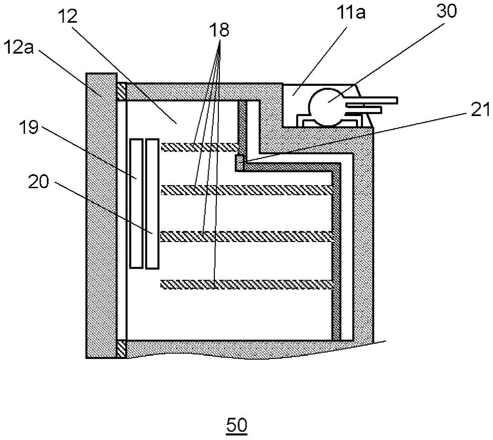
[0061] figure 1 It is a front view of refrigerator 50 in 1st Embodiment of this invention.

[0062] Such as figure 1 As shown, refrigerator 50 includes refrigerator main body 11 . The main body 11 of the refrigerator is a heat-insulating box, which mainly has an outer box made of steel plate, an inner box formed of resin such as ABS, and a heat-insulating material such as polyurethane provided in the space between the outer box and the inner box. insulation.

[0063] Refrigerator main body 11 is thermally insulated and divided into a plurality of storage rooms. Refrigerating room 12 is provided at the uppermost part, and ice making room 13 and switching room 14 are arranged side by side at the lower part of refrigerating room 12 . Freezer compartment 15 is disposed below ice making compartment 13 and switching compartment 14 , and vegetable compartment 16 is disposed at the lowest portion.

[0064] In the front of each storage compartment, a door is provided in the fron...

no. 2 Embodiment approach

[0203] Figure 17 It is a figure which schematically shows the refrigerant circuit of the refrigerator which concerns on 2nd Embodiment of this invention. Among them, the same configuration and the same technical idea as those described in detail in the first embodiment of the present invention can be applied in combination with this embodiment without inappropriate parts, and detailed descriptions are omitted.

[0204] Figure 17 In this case, the high-temperature, high-pressure refrigerant compressed by the compressor 30 is condensed in the condenser 81 and switched by the switching valve 74 downstream of the condenser 81 . And one side of the switching valve 74 communicates with the heat dissipation pipe 75 for preventing dew condensation arranged on the periphery of the front opening of the refrigerator, and then is decompressed by the capillary tube 83 , evaporates in the cooler 85 , and returns to the compressor 30 . In addition, the other side of the switching valve 7...

no. 3 Embodiment approach

[0231] Figure 18 It schematically shows the refrigerant circuit of the refrigerator which concerns on 3rd Embodiment of this invention. Among them, the same configuration and the same technical idea as those described in detail in Embodiments 1 and 2 can be used in combination with the present embodiment without inappropriate parts, and detailed descriptions are omitted.

[0232] Figure 18 In this case, the high-temperature, high-pressure refrigerant compressed by the compressor 30 is condensed in the condenser 81 and switched by the switching valve 92 downstream of the condenser 81 . One side of switching valve 92 is connected to cooler 94 for freezer compartment via capillary tube 93a, and the other side of switching valve 92 is connected to cooler 95 for refrigerator compartment via capillary tube 93b.

[0233] That is, it is characterized in that by providing the cooler 94 for the freezer compartment and the cooler 95 for the refrigerator compartment, switching the ref...


PUM


Abstract

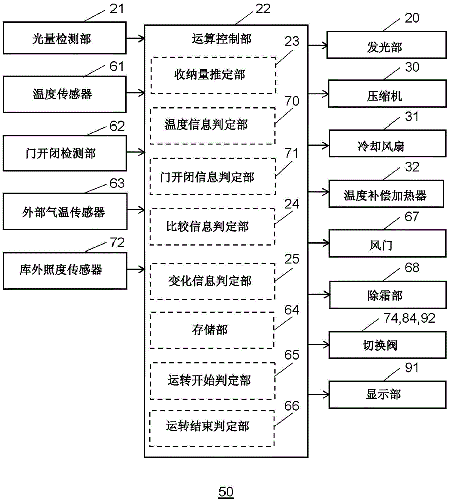
The present invention is equipped with: a refrigeration device that cools the interior of storage compartments; dampers (67) that control the supplied amount of cold air generated by the refrigeration device, and that correspond to each storage chamber; and a calculation control unit (22) that performs calculations on the basis of input data from a storage volume estimation unit (23) and a memory unit (64), and that controls the refrigeration device. In addition, normally an energy conservation operation is performed by controlling the damper (67) corresponding to each storage chamber, and when the storage volume has changed greatly due to bulk buying or the like, the amount of cooling of a chamber for which the storage volume has changed is increased by controlling the dampers (67), thereby cooling the introduced storage items to the optimum preservation temperature in a short amount of time.

Description

technical field [0001] The present invention relates to a refrigerator including means for detecting storage conditions of a storage room in a storage room of the refrigerator. Specifically, the present invention relates to a refrigerator capable of rapid cooling or automatic power saving by adjusting cooling capacity according to changes in storage conditions. Background technique [0002] In recent years, household refrigerators are equipped with a plurality of rooms with different temperature ranges such as refrigerators and freezers for storing various foods, and each room has an internal temperature sensor that detects the temperature of each room. As a result, the amount of cooling is adjusted, and temperature adjustment control is performed. [0003] For example, as a refrigerator that adjusts the cooling capacity of each chamber, there is a refrigerator in which a discharge port facing each chamber is provided with a damper that opens or blocks the supply of cold air...

Claims


Application Information

Patent Timeline
Patent Type & Authority Applications(China)
IPC IPC(8): F25D11/02F25D17/08F25D23/00F25D27/00
CPCF25D29/00F25D17/045F25D17/065F25D27/005F25D2500/04F25D2700/06F25D2700/12F25D11/02F25D17/08F25D23/00
Inventor 中川雅至上迫丰志柿田健一森贵代志
Owner PANASONIC INTELLECTUAL PROPERTY MANAGEMENT CO LTD
Learn More