
Chain Joints for Links

A technology of chains and links, applied in tow chains, hanging chains, chain buckles, etc., can solve the problems of wasting and cutting off links, increasing the use of raw materials, high cost, etc. amount of effect

Active Publication Date: 2016-11-09
PEWAG AUSTRIA
View PDF3 Cites 1 Cited by
  • Summary
  • Abstract
  • Description
  • Claims
  • Application Information

AI Technical Summary

Problems solved by technology

[0003] In this known chain joint, the body is designed circumferentially from round steel of constant cross-section and is produced at relatively high cost from round steel links, wherein the links used as blanks for the bodies of the chain joint Cutting from endless chains and wasting the cut links and increasing the use of raw materials

Method used


Image

  • Chain Joints for Links
  • Chain Joints for Links
  • Chain Joints for Links

Examples


Embodiment Construction

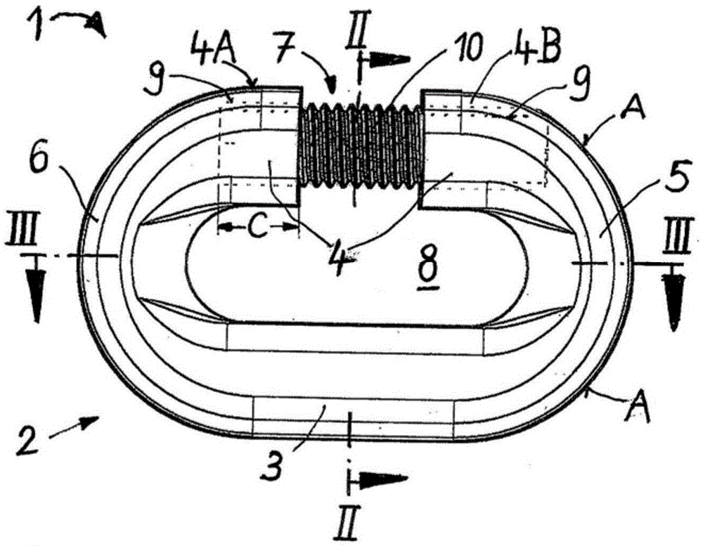
[0019] figure 1 A side view is shown of a chain joint 1 having a main body 2 designed substantially in the form of an oval link, the main body 2 comprising two longitudinal arms 3, 4 parallel to each other, each longitudinal arm via Bent loops 5 , 6 are connected to each other at their ends, wherein in the illustrated embodiment they are shown in side view forming a semicircle.

[0020] in one of the two longitudinal arms, i.e. in figure 1 Longitudinal arm 4 indicated at the top, a receiving opening 7 is formed in the middle which, when open, allows the oval link to be hooked to the inner opening 8 surrounded by the chain joint 1 or its body 2 .

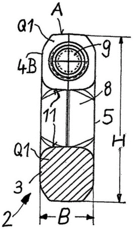
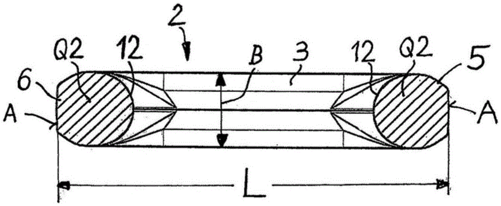
[0021] as from figure 1 and especially from Figure 4 It can be seen from the Figure 4 show figure 1 The three-dimensional diagonal representation of the main body 2 of the chain joint 1, the receiving opening 7 is attached to the middle part on the longitudinal arm 4 and is bounded by the longitudinal arm parts 4A and 4B respe...


PUM


Abstract

A chain joint for link chains, having a main body in the form of an oval chain link with two mutually parallel longitudinal legs which are connected to one another at their ends via a rounded link portion, one defining a receiving opening for receiving chain links. The receiving opening is bounded at its ends by one longitudinal leg section, wherein, in the longitudinal leg, a threaded bore runs in the longitudinal direction and extends in both longitudinal leg sections. A closure screw engages the threaded bore in both longitudinal leg sections, so that, while maintaining the predefined sizes for outer circumference and link width of the main body, the main body, in the region of its longitudinal legs, includes a profile cross section that is larger than the profile cross section in the region of its rounded link portions.

Description

technical field [0001] The invention relates to a chain joint for a chain link having a body in the form of an oval link with two longitudinal arms parallel to each other and each at its end via a curved loop connected together, wherein one of the longitudinal arms has a break, which is used to form a receiving opening for hooking the oval link into the internal opening of the main body, the receiving opening being defined by each longitudinal arm at its end Defining the boundary, wherein in the longitudinal arm a threaded hole continuing in the longitudinal direction of the longitudinal arm is provided, the threaded hole extending to both longitudinal arms to close the receiving opening, a closing bolt can be screwed into the thread In the screwed-in state, the closure bolt engages with threaded holes in the two longitudinal arms, wherein the dimensions of the outer circumference and ring width of the main body are preset. Background technique [0002] Chain joints of the ...

Claims


Application Information

Patent Timeline
Patent Type & Authority Patents(China)
IPC IPC(8): F16M13/04
CPCF16G15/04F16G13/12F16G15/02F16G15/06
Inventor 艾格伊德·彭格法兰兹·福斯
Owner PEWAG AUSTRIA
Learn More