Method for operating a charging station

A technology for charging stations and vehicles, applied in charging stations, electrical devices, electric vehicle charging technology, etc.

Inactive Publication Date: 2015-04-01
AUDI AG
View PDF4 Cites 3 Cited by
  • Summary
  • Abstract
  • Description
  • Claims
  • Application Information

AI Technical Summary

Problems solved by technology

[0007] Furthermore, for the vehicle manufacturer, costs for efficient encoding / decoding hardware also arise in the vehicle for this form of charging communication.

Method used


Image

  • Method for operating a charging station
  • Method for operating a charging station
  • Method for operating a charging station

Examples


Embodiment Construction

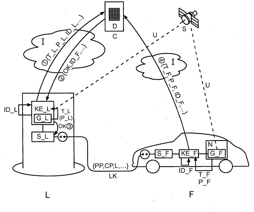
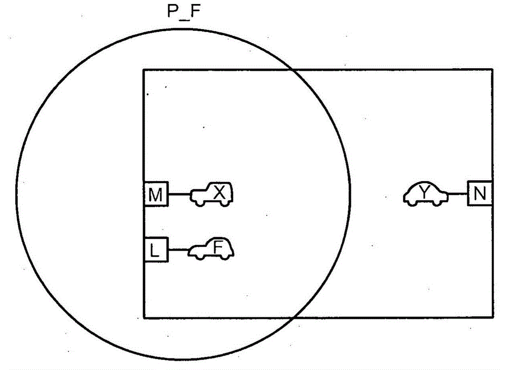
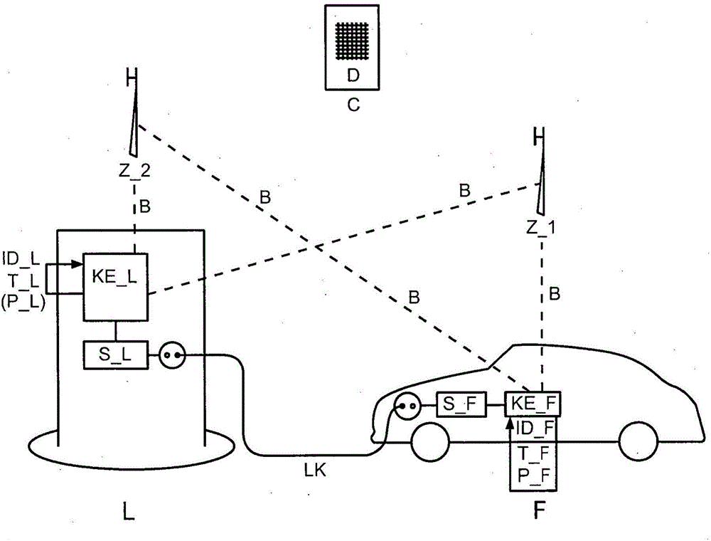
[0019] exist Figures 1 to 3 The method described below is exemplified in . In this method, at least one electric vehicle F or at least some electrically driven motor vehicles—the two terms below are used as synonyms—are recharged with electrical energy at a charging station L provided therefor. Charging station L generally refers to the charging infrastructure and therefore includes all possibilities for charging the electric vehicle F.

[0020] The electric vehicle F and the charging station L are brought close to each other for charging, wherein the vehicle F is preferably brought close to the charging station L. The actual charging process is not important to the method, so no further discussion of the different forms of charging is needed here. Note, however, that the method described will function in all forms of charging. In addition to wired charging, contactless charging also belongs to this category, such as inductive charging. Usually, for billing reasons, the c...


PUM


Abstract

The invention relates to a method for operating a charging station (L) which is designed for electrically charging an electrically powered vehicle (F), wherein the vehicle (F) is coupled to the charging station (L) for charging, wherein a time for the coupling of the vehicle (F) to the charging station (L) is documented separately at least by the vehicle (F) and the charging station (L).

Description

technical field [0001] The invention relates to a method for operating a charging station according to the preamble of independent claim 1 . Background technique [0002] In order to operate electric vehicles, it is necessary to make available a dense network of charging stations similar to the network of refueling stations for motor vehicles with internal combustion engines. The so-called electric vehicle charging infrastructure is therefore an important factor for the acceptance and thus the success of electric vehicles. For the approximately one million electric vehicles expected to be on German roads in 2020, a corresponding number of charging stations must be available. The infrastructure costs incurred for this are considerable compared to the charging systems currently in use, so a widespread infrastructure of charging stations will not be considered at present. [0003] The known systems are uncomfortable because the user must first be identified at the charging st...

Claims


Application Information

Patent Timeline
IPC IPC(8): B60L3/12B60L11/18G08C17/00H02J7/00
CPCB60L3/12B60L2240/622B60L2240/625B60L2240/70B60L2240/80Y02T90/16Y02T90/14Y04S30/12Y04S30/14B60L53/14B60L53/31B60L53/65B60L53/305B60L53/68Y02T10/7072Y02T10/72Y02T90/12Y02T10/70Y02T90/167
Inventor G·吕布A·克拉策尔
Owner AUDI AG
Why Eureka
Try Eureka