
Method and system for measuring monocular line-of-sight range of wearable glasses based on logo

A wearable glasses and identification technology, applied in mechanical mode conversion, input/output process of data processing, input/output of user/computer interaction, etc., can solve problems such as line-of-sight measurement

Active Publication Date: 2017-07-21
泰州祥云软件开发有限公司
View PDF4 Cites 0 Cited by
  • Summary
  • Abstract
  • Description
  • Claims
  • Application Information

AI Technical Summary

Problems solved by technology

[0005] Embodiments of the present invention provide a logo-based method and system for measuring the monocular sight range of wearable glasses to solve the problem of sight range measurement

Method used


Image

  • Method and system for measuring monocular line-of-sight range of wearable glasses based on logo
  • Method and system for measuring monocular line-of-sight range of wearable glasses based on logo

Examples


Embodiment l

[0031] Embodiment 1 A logo-based method and system for measuring the monocular line-of-sight range of wearable glasses.

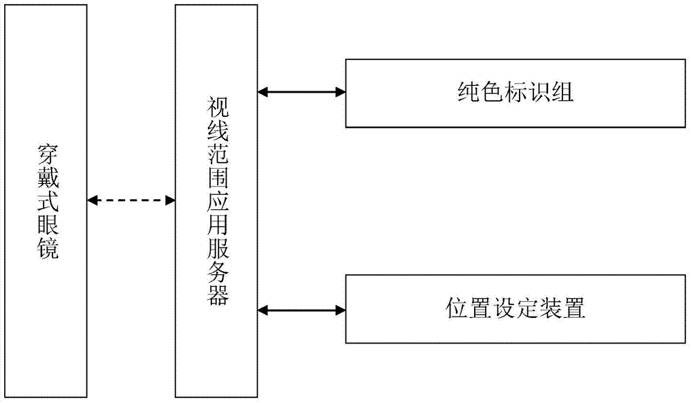
[0032] Such as figure 1 As shown, the embodiment of the present invention is based on the logo-based method and system for measuring the monocular line-of-sight range of wearable glasses, including a solid-color logo group, a position setting device, a line-of-sight application server, and wearable glasses.

[0033] Solid-color logo group, each solid-color logo is printed in one RGB color, and the RGB color code is printed on the back, and a solid-color logo group is composed of multiple solid-color logos of different RGB colors.

[0034] The position setting device consists of an indoor coordinate device and a two-dimensional code reading device. It is used to obtain the indoor position coordinates. The user reads the RGB color code on the back of the solid-color logo at any position indoors, and pastes the solid-color logo on the ground or wall. The coor...

Embodiment 2

[0049] Embodiment 2 Implementation steps of a method and a system for measuring the range of a monocular line of sight of wearable glasses based on a logo.

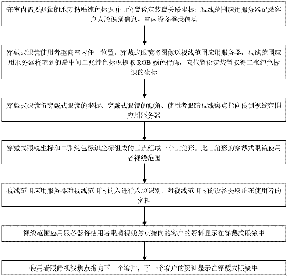
[0050] Such as figure 2 As shown, the embodiment of the present invention is based on the logo-based method and system for measuring the monocular line-of-sight range of wearable glasses, which is characterized in that the implementation steps are as follows.

[0051] Step 1: Paste a solid-color logo on the place to be measured indoors and set the device to associate coordinates with the position; the line-of-sight application server records the customer's face recognition information and indoor device login information.

[0052] Step 2: The user of the wearable glasses looks at any position in the room, and the wearable glasses send the image to the application server in the line of sight, and the application server in the line of sight extracts the RGB color codes from the two middlemost solid color signs seen, and sends...


PUM


Abstract

The invention discloses a wearable glasses monocular visibility range measuring method and system based on identifiers. The wearable glasses monocular visibility range measuring method and system comprises a pure color identifier set, a position setting device, a visibility range application server and wearable glasses. Each pure color identifier of the pure color identifier set is printed through one RGB color, and the back faces of the pure color identifiers are printed with RGB color codes. A user of the position setting device reads the RGB color codes on the back faces of the pure color identifiers at any indoor position, the pure color identifiers are pasted on the ground or a wall, and the coordinates of the pure color identifiers on the ground or the wall are associated with the RGB color codes, and transmitted to the visibility range application server. The wearable glasses are used for transmitting data to the visibility range application server, and receiving information of the visibility range application server. The visibility range application server comprises a service control device and an indoor image device and is used for sending corresponding messages to the user of the wearable glasses according to scenes and figures within the visibility range after the visibility range is obtained.

Description

technical field [0001] The invention relates to the technical field of monocular sight range measurement, in particular to a method and system for marking-based monocular sight range measurement of wearable glasses. Background technique [0002] For indoor environments, if the location coordinates within the line of sight can be determined, there are very rich applications. [0003] Because the wearable glasses can give real-time instructions to the bank account manager, the efficiency is greatly improved, but the wearable glasses cannot identify customers within the line of sight, so the banking server cannot provide correct guidance. [0004] However, if there is a technical solution that can identify the spatial position and direction of the wearable glasses user, the banking service server can choose the nearest customer to the wearable glasses user, and can also instruct the nearest Wearable glasses users provide targeted services for them. Further, if wearable glasses...

Claims


Application Information

Patent Timeline
Patent Type & Authority Patents(China)
IPC IPC(8): G06F3/01G06K7/00
CPCG06F3/011
Inventor 杨屹峰
Owner 泰州祥云软件开发有限公司
Learn More