
Array substrate, display panel and driving method thereof, display device

A technology of array substrates and display panels, applied in static indicators, instruments, nonlinear optics, etc., can solve the problem of high power consumption of display panels and achieve the effect of reducing power consumption

Active Publication Date: 2017-06-13
SHANGHAI TIANMA MICRO ELECTRONICS CO LTD +1
View PDF6 Cites 1 Cited by
  • Summary
  • Abstract
  • Description
  • Claims
  • Application Information

AI Technical Summary

Problems solved by technology

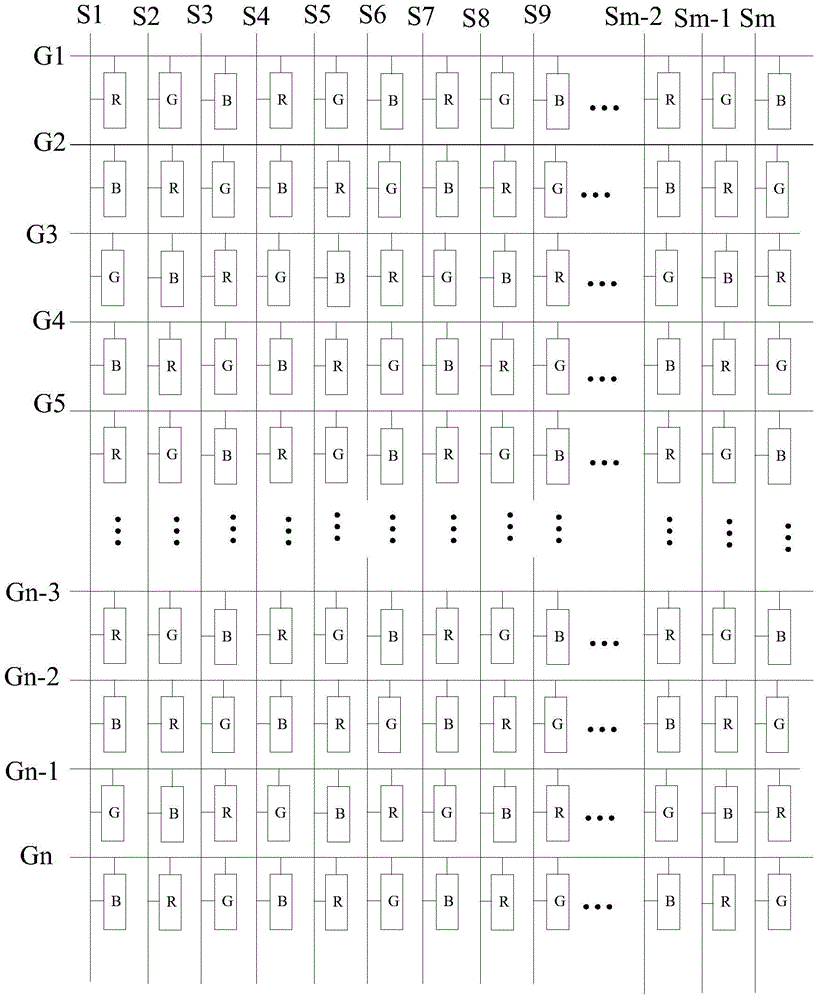
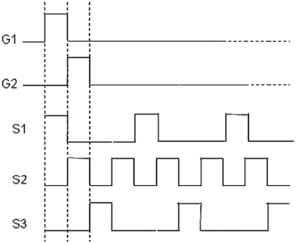
[0003] from figure 1 It can be seen from the figure that, in the display panel, the sub-pixel row corresponding to each scanning line G includes three sub-pixels of RGB, and the three sub-pixels of RGB are arranged in a circle, and the sub-pixel column corresponding to each data line S also includes Including RGB three kinds of pixels, and the first column of sub-pixels in RBGB circular arrangement, and the driving mode of each sub-pixel in the display panel is progressive scanning, so that when the display panel displays a monochrome picture, the voltage on the data line S It needs to change continuously to correspond to different colors. For example, when displaying a pure red screen, in the first column of sub-pixels, when G1 is turned on, S1 outputs the driving voltage required for R sub-pixel display to control the display of R sub-pixels. When When G2, G3, and G4 are turned on, S1 does not output the driving voltage required by the G sub-pixel and B sub-pixel, and controls the G sub-pixel and B sub-pixel to not display. When G5 is turned on, S1 outputs the drive required by the R sub-pixel again. Voltage to control the R sub-pixel display, and so on, during the progressive scanning of each frame display screen, the voltage on the data line needs to change continuously, and some of its timing diagrams are as follows figure 2 As shown, to control the display of each sub-pixel, resulting in higher power consumption of the display panel

Method used


Image

  • Array substrate, display panel and driving method thereof, display device
  • Array substrate, display panel and driving method thereof, display device
  • Array substrate, display panel and driving method thereof, display device

Examples


Embodiment Construction

[0036] As mentioned in the background art section, the power consumption of the display panel in the prior art is relatively high.

[0037] In view of this, an embodiment of the present invention provides an array substrate, including:

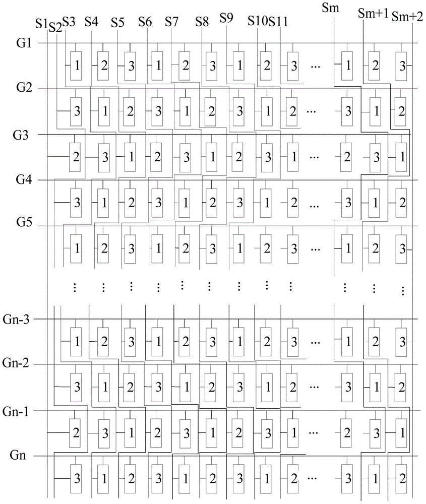
[0038] A plurality of sub-pixel units arranged in the row direction and the column direction, in the row direction, the sub-pixel units of N colors are arranged alternately and cyclically, and in the column direction, the sub-pixel units of different colors are arranged alternately and cyclically;

[0039] A plurality of data lines, each of which is electrically connected to sub-pixel units of the same color, and is electrically connected to at most one sub-pixel unit in each row of sub-pixels.

[0040] Correspondingly, the embodiments of the present invention also provide a display panel including the above-mentioned array substrate and a display device including the display panel.

[0041] In addition, an embodiment of the present invention...


PUM


Abstract

The invention discloses a display panel, a driving method of the display panel and a display device. An array substrate comprises a plurality of sub-pixel units and a plurality of data lines. The sub-pixel units are arrayed in the row direction and the list direction, and in the row direction, the sub-pixel units with N sorts of colors are arrayed in an alternately cyclic mode; in the list direction, the sub-pixel units of different colors are arrayed in an alternately cyclic mode. Each data line is electrically connected with the sub-pixel units of the same color, and at most one sub-pixel unit is electrically connected into each row of sub pixels. According to the array substrate, each data line is electrically connected with the sub-pixel units of the same color, the sub-pixel units of different colors are electrically connected to different data lines, hence, when the display panel including the array substrate displays full-color images, in the row-by-row scanning process of each frame of display picture, each data line only needs to provide the voltage corresponding to the sub pixels of the same color, the potential does not need to be changed all the time, and therefore the power consumption of the display panel is lowered.

Description

technical field [0001] The present invention relates to the field of display technology, and in particular to an array substrate, a display panel including the array substrate, a driving method thereof, and a display device including the display panel. Background technique [0002] Such as figure 1 As shown, the display panel in the prior art includes: a plurality of scanning lines G, a plurality of data lines S, and a plurality of mutually perpendicular sub-pixel rows and sub-pixel columns, wherein one scanning line G corresponds to one row of sub-pixels, and is used to control the For the opening and closing of row sub-pixels, one data line S corresponds to a column of sub-pixels, and is used to provide a driving signal to the sub-pixels in the on-state of the column of sub-pixels to control the display of the sub-pixels. [0003] From figure 1 It can be seen from the figure that, in the display panel, the sub-pixel row corresponding to each scanning line G includes thre...

Claims


Application Information

Patent Timeline
Patent Type & Authority Patents(China)
IPC IPC(8): G02F1/1362G02F1/133
CPCG02F1/1362G02F2201/52G09G3/3611
Inventor 王亚杰周井雄
Owner SHANGHAI TIANMA MICRO ELECTRONICS CO LTD
Learn More