
Anchorage pier structure suitable for surrounding rock deformation

A technology for anchor pier structure and surrounding rock deformation, which is applied in the direction of foundation structure engineering, building, sheet pile wall, etc., can solve the problems of inconvenient operation, insufficient supporting force, heavy workload, etc., and achieve the purpose of avoiding instability of surrounding rock, The effect of simple and convenient construction and simple structure

Active Publication Date: 2015-04-01
CHINA HYDROELECTRIC ENGINEERING CONSULTING GROUP CHENGDU RESEARCH HYDROELECTRIC INVESTIGATION DESIGN AND INSTITUTE
View PDF4 Cites 9 Cited by
  • Summary
  • Abstract
  • Description
  • Claims
  • Application Information

AI Technical Summary

Problems solved by technology

[0006] However, the above measures all have obvious defects: the shortcoming of measure 1 is mainly that the surrounding rock deformation cannot be well reserved
If the reserved tonnage of the anchor cable design is too large, the initial support force will be insufficient, and the surrounding rock may become unstable; if the reserved tonnage of the anchor cable design is too small, the reserved deformation will be too small, resulting in the later anchor cable being easily overloaded
In addition, the general anchor cable can only allow a deformation of 10-20mm, which does not match the deformation of the surrounding rock in the later stage, which generally exceeds 30-40mm, and even reaches 70-80mm.
The disadvantage of measure 2 is mainly that it is difficult to relax and stretch in the later stage
When the steel strands have been stretched, loosening the steel strands may cause damage to the steel strands; at the same time, loosening and stretching the steel strands in batches in the later stage requires a large workload and is inconvenient to operate

Method used


Image

  • Anchorage pier structure suitable for surrounding rock deformation

Examples


Embodiment Construction

[0019] The present invention will be further described below in conjunction with the accompanying drawings and specific embodiments.

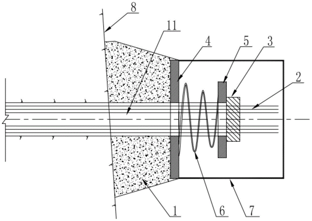
[0020] Such as figure 1 As shown in , the anchor pier structure suitable for surrounding rock deformation according to the present invention includes an anchor pier 1, a steel strand 2 and an anchorage 3; one end of the steel strand 2 passes through the locking hole on the anchor pier 1 After 11, it is locked on the anchor pier 1 by the anchor 3; it is characterized in that it also includes the first anchor plate 4, the second anchor plate 5 and the elastic member 6; the first anchor plate 4 and the second anchor plate 5 are arranged on Between the anchor pier 1 and the anchorage 3, the steel strand 2 passes through the locking hole 11 on the anchorage pier 1, then passes through the first anchor plate 4, the second anchor plate 5, and finally connects with the anchorage 3; the elastic The piece 6 is arranged between the first anchor plate 4 a...


PUM


Abstract

The invention discloses an anchorage pier structure suitable for surrounding rock deformation, belonging to the field of building construction. The anchorage pier structure suitable for surrounding rock deformation comprises an anchorage pier, a steel strand and an anchorage device, wherein one end of the steel strand penetrates through a locking hole on the anchorage pier and is locked on the anchorage pier through the anchorage device; the anchorage pier structure further comprises a first anchorage plate, a second anchorage plate and an elastic part, wherein the first anchorage plate and the second anchorage plate are arranged between the anchorage pier and the anchorage device; the steel strand penetrates through the lock hole in the anchorage pier, then penetrates through the first anchorage plate and the second anchorage plate in sequence, and is finally connected to the anchorage device; the elastic part is arranged between the first anchorage plate and the second anchorage plate. The self-adaptive regulation of the anchorage pier structure during surrounding rock deformation is realized, so that enough anchorage force can be provided at an initial anchorage stage, and therefore, the surrounding rocks are prevented from being unstable; meanwhile, enough deformation can be reserved for being adaptive to the great deformation condition which possibly appears in later-stage surrounding rocks. Besides, the anchorage rope is prevented from being stretched and pulled for the second time.

Description

technical field [0001] The invention relates to the field of building construction, in particular to an anchor pier structure suitable for surrounding rock deformation. Background technique [0002] With the development of western water conservancy projects, hydropower projects and traffic projects, more and more underground projects will need to be built. Under the special geological and terrain conditions in the west, the problem of high ground stress often plagues the design of underground engineering and excavation support construction, and may affect the long-term stability of the surrounding rock of underground caverns. [0003] In the support design of the surrounding rock of underground caverns, prestressed anchor cables are often used. Under the condition of high ground stress, the deformation of the surrounding rock is generally large in the later stage. If the anchor cable is stretched to the design tonnage at the initial stage, the surrounding rock will graduall...

Claims


Application Information

Patent Timeline
Patent Type & Authority Applications(China)
IPC IPC(8): E02D5/74
CPCE02D5/74
Inventor 肖平西范祥伦廖成刚幸享林侯东奇邓兴富王波刘瑞雪
Owner CHINA HYDROELECTRIC ENGINEERING CONSULTING GROUP CHENGDU RESEARCH HYDROELECTRIC INVESTIGATION DESIGN AND INSTITUTE
Learn More