Filter tube ejection device

A filter tube and mold technology, applied in the field of filter tube ejection device, can solve the problems of low processing efficiency, inability to complete demoulding, increase of mold cost, etc., achieve high processing efficiency, and avoid the effects of cooling and normal demoulding

Active Publication Date: 2017-04-12
萍乡市普天高科实业有限公司
View PDF5 Cites 0 Cited by
  • Summary
  • Abstract
  • Description
  • Claims
  • Application Information

AI Technical Summary

Problems solved by technology

And in order to improve production efficiency, several cavities are often set in a pair of molds to complete the production of multiple filter tubes at the same time, but in this prior art, the mold-out process still uses the way of one-by-one mold-out, Therefore, the processing efficiency is low, and because the time interval between different filter tubes is too long, the filter tube that is released from the mold has cooled and shrunk in the mold cavity before the core-pulling is completed, so that the filter tube shrinks and tightens the core-pulling body, unable to complete demoulding
In addition, in the prior art, there is also the purpose of automatic product demoulding by directly setting the demoulding mechanism on the forming mold, but this prior art is not suitable for the demoulding of multi-cavity strip-shaped products in this field , because the dense molding cavity not only requires the precise cooperation between the demoulding mechanism and the mold opening and closing action to avoid mutual collision, so the structural design is more complicated, but also too many through holes need to be added on the mold, which also greatly increases the mold The cost of processing, reducing the accuracy of the molding surface of the mold and the strength of the mold

Method used


Image

  • Filter tube ejection device
  • Filter tube ejection device
  • Filter tube ejection device

Examples


Embodiment Construction

[0022] The present invention will be further described below in conjunction with the accompanying drawings and specific embodiments.

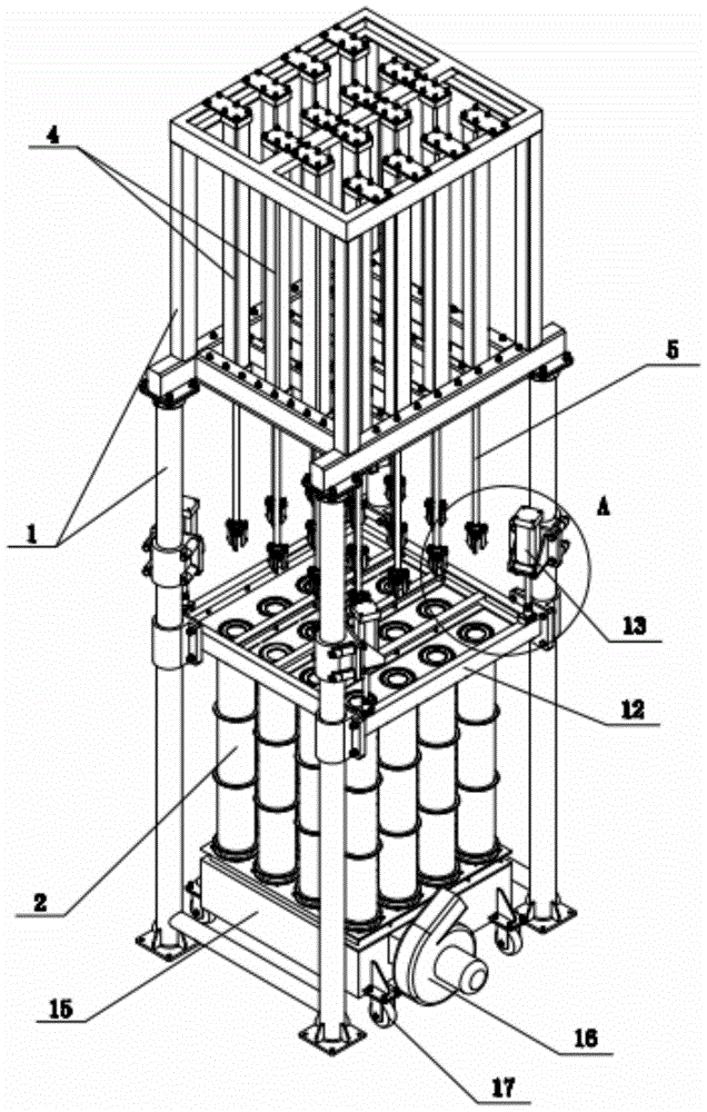
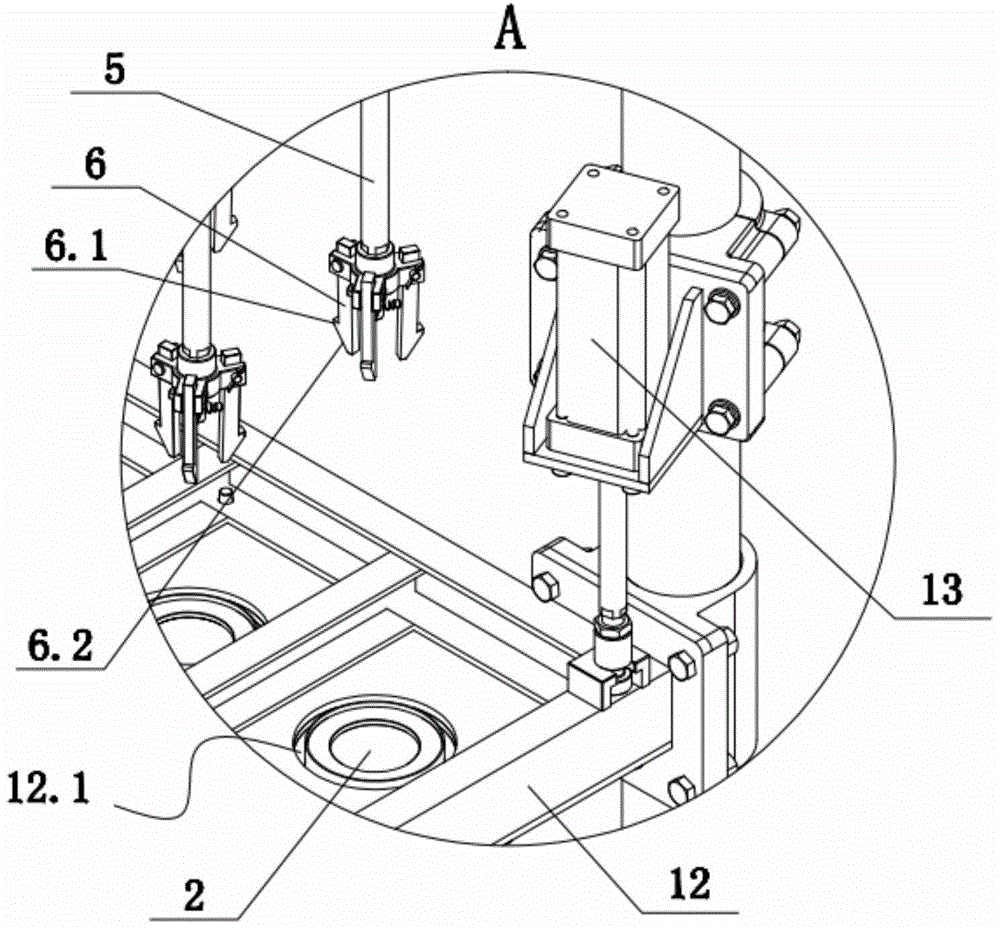
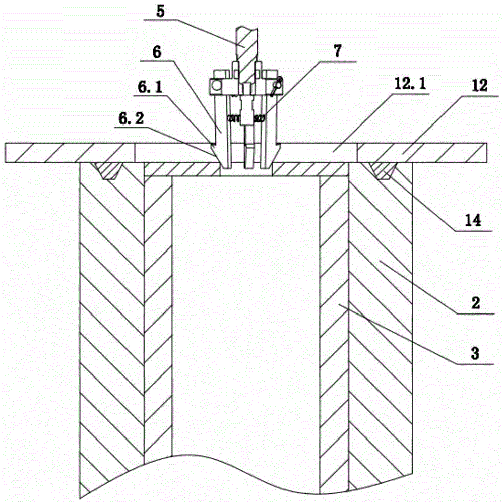
[0023] As shown in the figure, the present invention provides a filter pipe ejection device, which includes a bracket 1, a clamping mechanism arranged on the bracket 1 for fixing the mold 2, and a driver 4 is arranged above the mold 2 on the bracket 1 , the connecting rod 5 and the head-grabbing mechanism for grasping the filter tube 3, the driver 4 is fixed to the support 1, the power output end of the driver is connected to the upper end of the connecting rod 5, and the lower end of the connecting rod 5 extends to the top of the filter tube 3, and grasps The lower end of head mechanism and connecting rod 5 is fixed. The above-mentioned mold 2 refers to the template with the filter tube 3 after the mold is opened. The filter tube 3 has not been demolded and is still placed in the cavity of the mold 2. The mold 2 together with the filter tube 3...


PUM


Abstract

The invention discloses a mold stripping device for a filter pipe. The mold stripping device comprises a bracket (1) and a clamping mechanism arranged on the bracket (1) for fixing a mold (2), wherein the a driver (4), a connecting rod (5) and a gripper mechanism which is used for clamping a filter pipe (3) are arranged on the bracket (1) and located above the mold (2); the driver (4) is fixed with the bracket (1); the power output end of the driver is connected with the upper end of the connecting rod (5); the lower end of the connecting rod (5) extends to be above the filter pipe (3); the gripper mechanism is fixed with the lower end of the connecting rod (5). The invention provides the mold stripping device of the filter pipe, which has the advantages that the synchronous mold stripping of a plurality of filter pipes of the same molded cavity can be realized so as to guarantee high processing efficiency, and the phenomenon that mold stripping cannot be carried out due to the cooling of the filter pipes can be avoided.

Description

technical field [0001] The invention relates to auxiliary equipment for processing filter tubes, in particular to a filter tube ejection device. Background technique [0002] With the progress of industrial development, in the existing technology, the more conventional manufacturing process of the filter tube is to integrally form the filter tube through the cavity. Taking the ceramic filter tube as an example, the ceramic raw material is first heated to become a fluid, and the ceramic raw material is mixed with Fill in the foaming agent, then inject the heated raw material into the cavity of the mold through the sprue, and finally open the mold to take out the filter tube, and let it stand for cooling. During this process, a number of micropores are formed on the wall of the filter tube by the foaming agent. And in order to improve production efficiency, several cavities are often set in a pair of molds to complete the production of multiple filter tubes at the same time, ...

Claims


Application Information

Patent Timeline
Patent Type & Authority Patents(China)
IPC IPC(8): B28B21/90
CPCB28B21/90
Inventor 黄新群黄乃乔黄优良
Owner 萍乡市普天高科实业有限公司
Why Eureka
Try Eureka