X-Ray drilling device

A technology of drilling device and drilling mechanism, which is applied to laser welding equipment, printed circuits, manufacturing tools, etc., can solve the problems of unfavorable high-precision alignment production, poor quality of punched hole shape, and inability to achieve punching, etc. The effect of improving drilling quality, improving work efficiency and simple structure

Active Publication Date: 2015-04-01
GUANGZHOU FASTPRINT CIRCUIT TECH +2
View PDF5 Cites 1 Cited by
  • Summary
  • Abstract
  • Description
  • Claims
  • Application Information

AI Technical Summary

Problems solved by technology

[0003] At present, the X-Ray punching machine in the industry is mainly used for positioning holes on the edge of the board. For the position target in the board, most of them can only use the method of punching the target. This method is slow in punching speed, low in efficiency, and the knife is released after drilling The quality of the face shape is poor, which is not conducive to the local high-precision alignment production requirements; in addition, the structure of the existing X-Ray punching machine is a double-axis type or a central suction vacuum type, which cannot punch holes at any position, and there are drilling blind spots

Method used


Image

  • X-Ray drilling device
  • X-Ray drilling device

Examples


Embodiment Construction

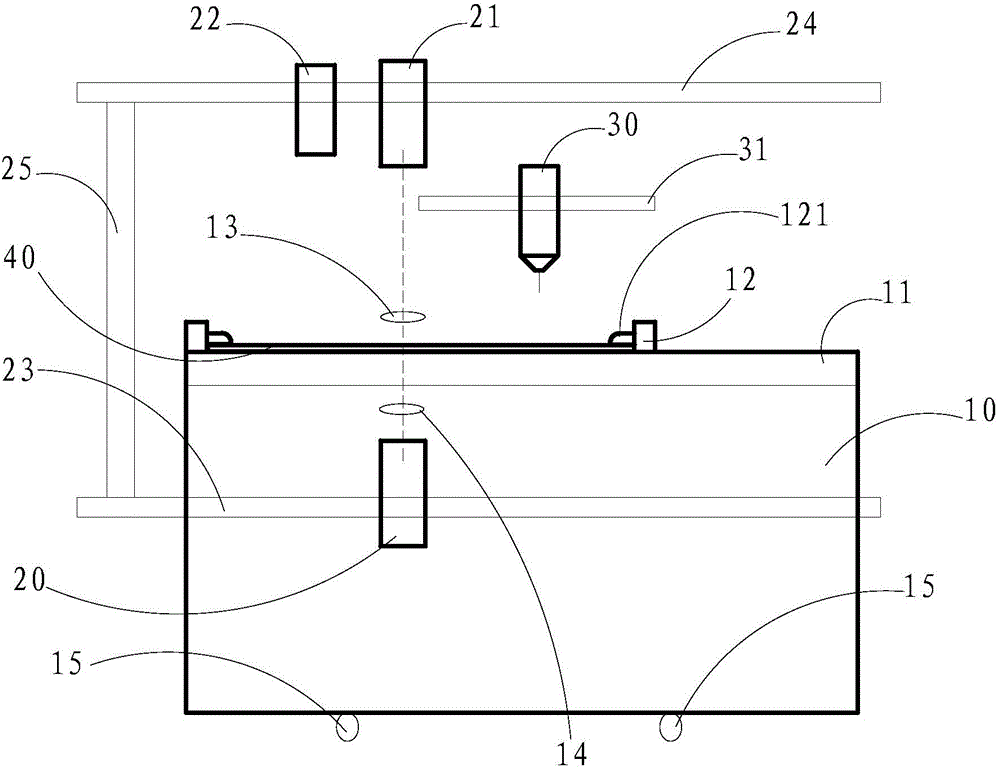
[0030] Such as figure 1 As shown, the X-Ray drilling device of the present invention includes a workbench 10, a first guide rail 15, a first drive mechanism (not shown in the figure), and the workbench 10 is connected with a The worktable 10 is connected to the first guide rail 15 , and the first driving mechanism is used to drive the workbench 10 to move along the first guide rail 15 .

[0031] The X-Ray drilling device of the present invention also includes a second drive mechanism (not shown in the figure), a second guide rail 23 and a third guide rail 24 arranged parallel to each other, the second guide rail 23, the third guide rail 24 Both have an included angle with the first guide rail 15 , and in the embodiment of the present invention, the second guide rail 23 and the third guide rail 24 are vertically arranged with the first guide rail 15 . And the second guide rail 23 is located below the first pressing structure 12, the third guide rail 24 is located above the fir...


PUM


Abstract

The invention relates to an X-Ray drilling device. The X-Ray drilling device comprises a worktable, a first guide rail and a first drive mechanism, wherein the worktable is connected with a first pressing structure; the first drive mechanism is used for driving the worktable to move along the first guide rail; the second guide rail and a third guide rail are both arranged in a manner of being vertical to the first guide rail and are respectively positioned on the two sides of the first pressing structure; a second drive mechanism is used for driving an X-Ray transmitter to move along the second guide rail and driving an X-Ray receiver to move along the third guide rail; a drilling mechanism is connected with a fourth guide rail; the third drive mechanism is used for driving the drilling mechanism to move along the fourth guide rail. Therefore, the X-Ray drilling device disclosed by the invention is simple in structure, overcomes the limitation that a plate edge is only drilled in the prior art, can be used for implementing steps of punching and drilling at any position on a PCB, and is high in automation degree, accurate in drilling position and beneficial for improving the work efficiency of plate drilling.

Description

technical field [0001] The invention relates to a drilling device, in particular to an X-Ray drilling device. Background technique [0002] In the PCB manufacturing process, in order to meet the local high-precision alignment requirements, X-Ray is often used to punch the local reference target first, and then use the quadratic element or an instrument with similar measurement functions to measure the expansion and contraction value of the reference target, and finally use this expansion and contraction value to compensate Drilling tape to achieve drilling of PCB boards. [0003] At present, the X-Ray punching machine in the industry is mainly used for positioning holes on the edge of the board. For the position target in the board, most of them can only use the method of punching the target. This method is slow in punching speed, low in efficiency, and the knife is released after drilling The quality of the face shape is poor, which is not conducive to the local high-preci...

Claims


Application Information

Patent Timeline
IPC IPC(8): B26F1/16B26D5/02B26D7/00B26D7/02B23K26/382
CPCB23K2101/42B26D5/02B26D7/02B26F1/16
Inventor 任小浪樊光辉陈蓓
Owner GUANGZHOU FASTPRINT CIRCUIT TECH
Why Eureka
Try Eureka