
Centrifugal ball clamping fixture

A technology of clamping clamps and balls, applied in the direction of expanding the mandrel, etc., which can solve the problems of easy deformation of thin-walled cylinders

Inactive Publication Date: 2015-04-01
常州市文每机械配件厂
View PDF0 Cites 5 Cited by
  • Summary
  • Abstract
  • Description
  • Claims
  • Application Information

AI Technical Summary

Problems solved by technology

In summary, there is no special fixture for thin-walled cylinders in machining, resulting in easy deformation of thin-walled cylinders

Method used


Image

  • Centrifugal ball clamping fixture

Examples


Embodiment Construction

[0012] The present invention will be further described below in conjunction with the accompanying drawings and specific embodiments.

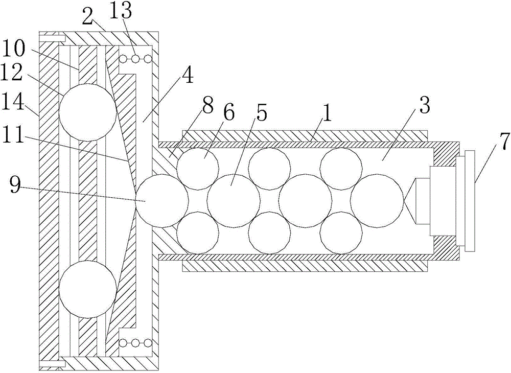
[0013] Such as figure 1 , a centrifugal ball clamping fixture, including an expansion sleeve mandrel 1, one end of the expansion sleeve mandrel 1 is connected with a housing 2, and a first cavity 3 is provided inside the expansion sleeve mandrel 1, and the first cavity 3 is equipped with Full of steel balls, a limit step 8 is provided in the first cavity 3 at one end of the connection with the shell 2, and the other end of the expansion sleeve mandrel 1 seals the first cavity 3 through the movable part 7 that is movably connected with it, and the shell The body 2 is provided with a second cavity 4, the first cavity 3 and the second cavity 4 are connected by the first ball 9, the first ball 9 and the limit step 8 are formed to isolate the first cavity 3 and the separation wall of the second cavity 4, the second cavity 4 is provided with an auto...


PUM


Abstract

The invention relates to a centrifugal ball clamping fixture comprising an expanding sleeve type mandrel. One end of the coupling mandrel is connected to a housing, the coupling mandrel is provided with a first cavity fulfilled with steel balls, one end of the first cavity, at the connecting position with the housing, is provided with a limit step inside, and the other end of the expanding sleeve type mandrel seals the first cavity through a movably-connected moving part; the housing is provided with a second cavity inside; the first cavity and the second cavity are connected through a first ball, and the first ball and the limit step form a partitioning wall partitioning the first cavity and the second cavity; the second cavity is provided with an automatic extruding device used for extruding the first ball to move in a reciprocating manner. The centrifugal ball clamping fixture has the advantages that the fixture is simple in structure and convenient to use and is capable of clamping thin-wall cylindrical workpieces rapidly and tightly.

Description

technical field [0001] The invention relates to the technical field of tooling, in particular to a centrifugal force ball clamping fixture. Background technique [0002] The thin-walled cylinder is rolled from a thin steel plate, so the thin-walled cylinder is very easy to deform. The two ends of the thin-walled cylinder need to be machined. Since the thin-walled cylinder is a deformable part, the thin-walled cylinder cannot be directly clamped on the machine tool. This requires the design of special fixtures to solve the problem of deformation of the existing thin-walled cylinder. To sum up, there is no special tooling and fixture for thin-walled cylinders in machining, which leads to easy deformation of thin-walled cylinders. Contents of the invention [0003] In view of the above problems, the object of the present invention is to provide a steel ball clamping fixture with simple structure and convenient use for quickly clamping thin-walled cylindrical workpieces. [...

Claims


Application Information

Patent Timeline
Patent Type & Authority Applications(China)
IPC IPC(8): B23B31/40
CPCB23B31/40
Inventor 陈文斌
Owner 常州市文每机械配件厂
Learn More