Battery-free meter for flowing media

A technology of flowing medium and measuring instrument, which is applied in the field of passive measuring instruments for flowing medium, can solve the problems of being easily affected by external magnetic fields and layout, and achieve the effect of improving operation safety, prolonging life and improving life.

Inactive Publication Date: 2015-03-25
HENGSTLER GMBH
View PDF8 Cites 3 Cited by
  • Summary
  • Abstract
  • Description
  • Claims
  • Application Information

AI Technical Summary

Problems solved by technology

[0008] The disadvantage of this known principle of use is the magnetic coupling, which is associated with higher costs and can be very easily influenced by external magnetic fields, which however is undesirable in gas meter construction or in water meter construction
[0009] A further disadvantage in the case of the prior art according to FIG. 1 is that the movable parts are arranged in the outer area, which is undesirable

Method used


Image

  • Battery-free meter for flowing media
  • Battery-free meter for flowing media
  • Battery-free meter for flowing media

Examples


Embodiment Construction

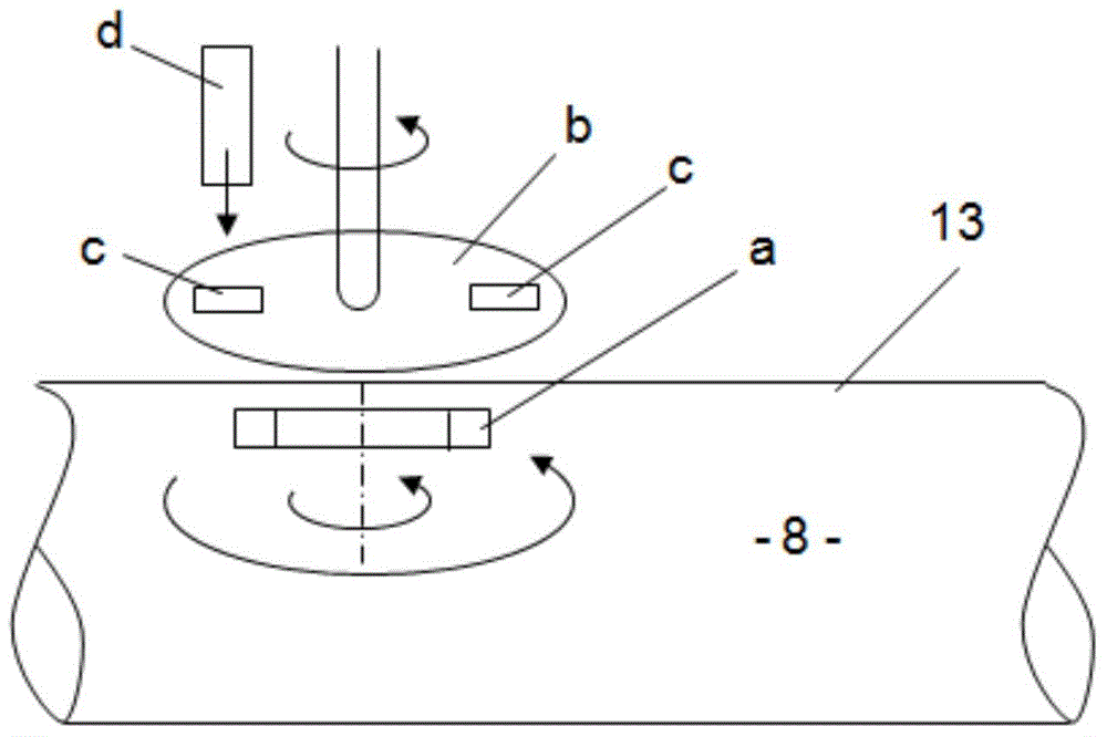
[0052] 1 shows schematically according to the prior art that a disk a carrying permanent magnets rotates in the flowing medium 8 and thereby generates a partition wall 13 passing through the medium to a space located outside the medium. A magnetic field on an additional rotatable disk b carrying one or more permanent magnets c, wherein there is a magnetic rotational coupling between disk a and disk b.

[0053] Through the rotation of disk a, disk b is rotationally driven via magnetic coupling and a Wiegand sensor d is arranged near disk b, whose Wiegand wire is loaded by the permanent magnetic field of permanent magnet c, so that in the case of a change in field direction Generate voltage pulses.

[0054] A disadvantage of the known device is the magnetic coupling through the partition wall 13 of the flow medium 8 .

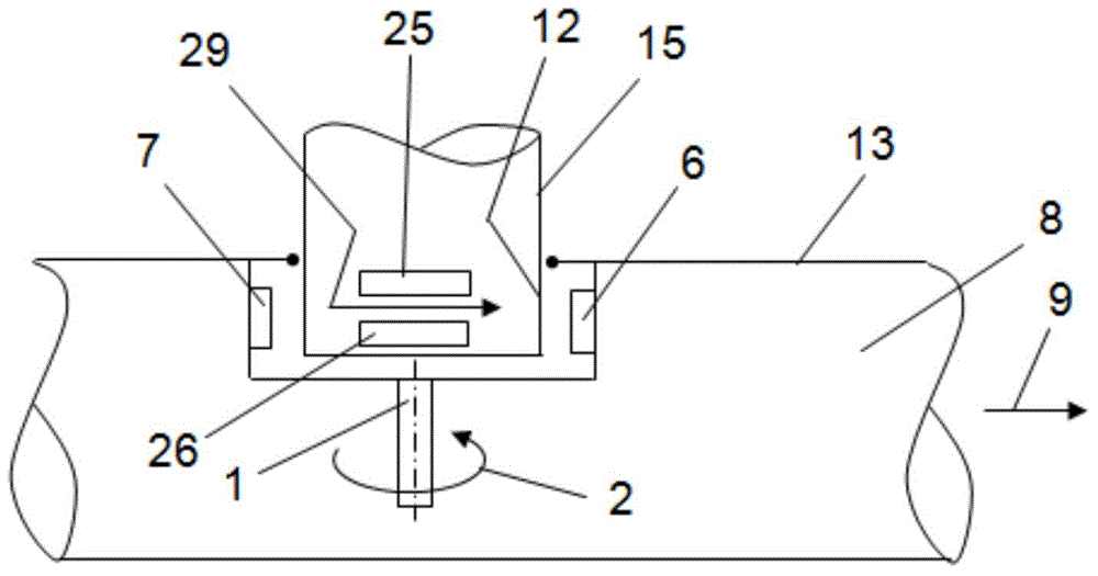
[0055] exist figure 2 The basic principle of the invention is shown in . According to the invention, the housing part 15 with the inner sleeve 12 is immersed ...


PUM


Abstract

Battery-free meter for flowing media, in which a rotor body (sleeve 4) which is fitted with permanent magnets (6, 7) and is driven in a rotary fashion by the medium is arranged in the pipeline (34) carrying the flowing medium (8) and in which the rotating magnetic field generated by this acts on at least one Wiegand sensor (25, 26), which is arranged outside the flowing medium in the area around the meter, wherein a housing part (15) which is open on at least one side sealing to the interior of the pipeline (34) engages with the pipeline (34) and around which the flowing medium at least partially flows, such that the external periphery of the housing part (15) is at least partially embraced by the rotor part (sleeve 4) which is driven in a rotary fashion and generates the rotating magnetic field and that at least one Wiegand sensor (25, 26) is arranged in the housing part (15).

Description

technical field [0001] The object of the invention is a passive metering device for flowing media according to the preamble of patent claim 1 . Background technique [0002] No. 6,612,188 B2 discloses a passive metering device for a flowing medium, in which a disk carrying permanent magnets and driven in rotation by the medium is arranged in the flowing medium. The Wiegand sensors necessary for generating the electrical energy are arranged outside the flow medium in the surrounding area of ​​the measuring device. [0003] The disadvantage of this arrangement is that only a single Wiegand sensor is provided. Therefore, the construction of a redundant system with two Wiegand sensors operating independently of each other is not possible. [0004] The concept of a "Wiegan sensor" is often synonymous with the concept of a "pulsed wire-motion sensor". For simplicity, only the first mentioned concepts are used in the following description. [0005] In the case of the object of ...

Claims


Application Information

Patent Timeline
Patent Type & Authority Applications(China)
IPC IPC(8): G01F1/075G01P3/481G01P3/488G01F1/115G01F15/14
CPCG01F1/075G01F1/115G01F15/14G01F1/586
Inventor 乔治·艾菲莫夫迈克尔·密克斯内尔
Owner HENGSTLER GMBH
Why Eureka
Try Eureka