
Outdoor LED driving power supply

A technology of LED drive and power supply, applied in the direction of electric light source, light source, electric lamp circuit layout, etc., can solve the problems of reduced production efficiency, high cost, unfavorable environmental protection, etc., to ensure the sealing effect, ensure the heat dissipation effect, and facilitate the production.

Inactive Publication Date: 2015-03-25
胡建龙
View PDF5 Cites 9 Cited by
  • Summary
  • Abstract
  • Description
  • Claims
  • Application Information

AI Technical Summary

Problems solved by technology

[0003] 1. The cost is high. Due to the high price of silica gel raw materials, pouring silica gel into the power supply can have a good heat dissipation effect, but it also leads to high product costs.
[0004] 2. Difficult to repair, because the circuit board is encapsulated in the power supply box through silica gel, the box body and the circuit board form a whole that cannot be disassembled. If there is a problem with the circuit in the circuit board, it cannot be repaired at all, and the entire power supply can only be scrapped , which causes huge waste and is not conducive to environmental protection
[0005] 3. The production process is complicated. Since the current production method needs to be filled with silica gel, the production process is increased and the production efficiency is reduced.
[0006] The inventor once proposed a Chinese invention patent for LED driving power to solve the defects of the existing technology, but this LED driving power still needs to be improved. This outdoor LED driving power is currently mainly used for LED lighting fixtures. In the actual use of the driving power supply, it is often necessary to adjust parameters such as the brightness of the LED lighting source through the adjustment knob in the power supply. hole, so it cannot be adjusted directly from the outside, and the power supply case must be opened to adjust, which will cause great trouble to the user

Method used


Image

  • Outdoor LED driving power supply
  • Outdoor LED driving power supply
  • Outdoor LED driving power supply

Examples


Embodiment Construction

[0025] Below in conjunction with accompanying drawing, this real type is described further:

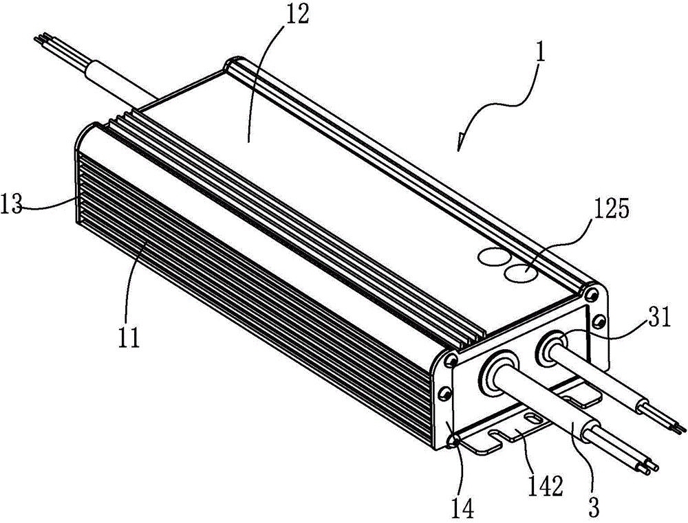
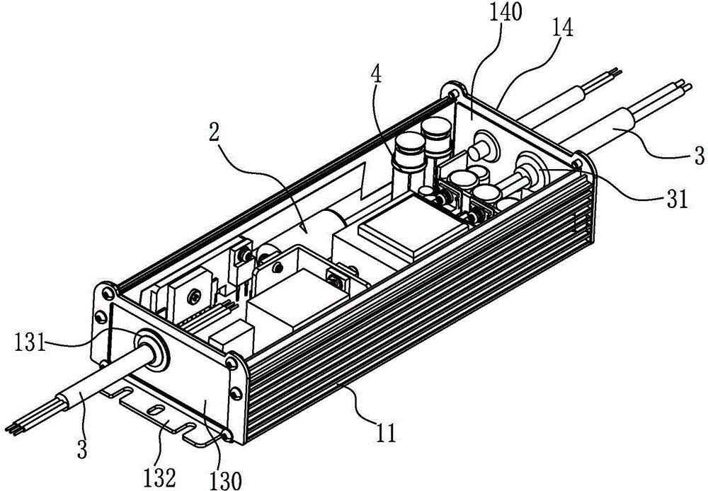
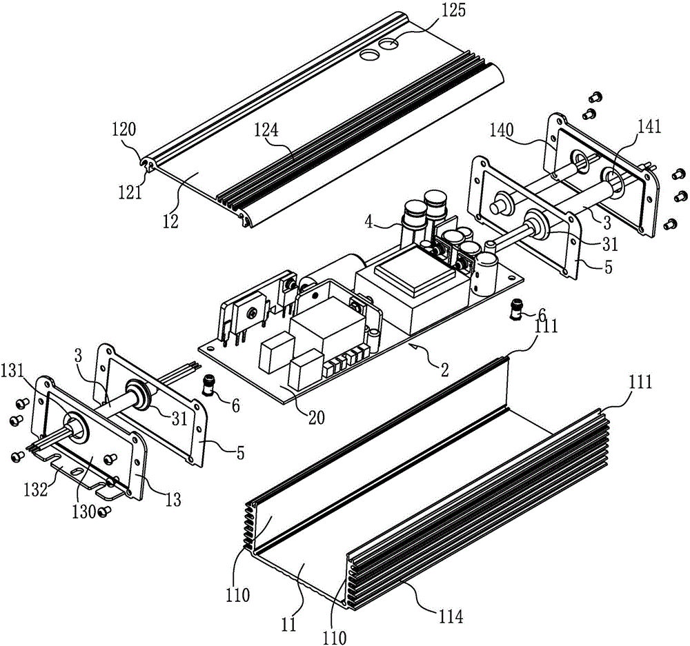
[0026] See Figure 1-6 , the present invention includes: a casing 1 and a power supply body 2 installed in the casing 1 .

[0027] The shell 1 includes: a cylindrical body composed of a lower housing 113 and an upper cover plate 12, and left and right cover plates 13, 14 encapsulated in ports on both sides of the cylindrical body, the upper cover plate 12 and the The lower casings 11 are fixed by clamping, and a sealant is provided at the clamping joint; the left and right cover plates 13, 14 are fixed on the left and right sides of the cylindrical body by screws, and are provided on the joint surface. There is a sealing rubber pad 5; the left and right cover plates 13, 14 are provided with through holes 131, 141 for the cable 3 to pass through, and a hard plastic ring 31 is clamped and fixed at the through holes 131, 141 , the cable 3 is passed through the plastic ring 31, and an i...


PUM


Abstract

The invention discloses an outdoor LED driving power supply. Through holes allowing a cable to penetrate through are formed in a left cover plate and a right cover plate of the LED driving power supply, hard plastic rings are embedded and fixed into the through holes, the cable penetrates through the plastic rings, and the cable and the plastic rings are in interference fit. An adjusting knob is arranged in a power supply body, the adjusting knob is fixedly packaged by a plastic sleeve, an adjusting hole is formed in the position, corresponding to the plastic sleeve, of an upper cover plate, the upper end of the plastic sleeve stretches to the adjusting hole, and a threaded plug for blocking a channel of the plastic sleeve is installed in the plastic sleeve. The adjusting hole is formed, the plastic sleeve is arranged in the adjusting hole, the adjusting knob can be directly adjusted from the outside, and dual waterproof protection can be achieved for the plastic sleeve through the threaded plug and an end cover in the plastic sleeve. In the outdoor LED driving power supply, when a wire penetrates through a baffle, a special sealing structure is adopted, no water leakage phenomenon is generated in the position of the wire, and the sealing performance of a product is further guaranteed.

Description

Technical field: [0001] The invention relates to the technical field of power supply products, in particular to an outdoor LED driving power supply with waterproof effect. Background technique: [0002] Due to the advantages of energy saving and environmental protection of LED lighting fixtures, many outdoor lighting fixtures are currently replaced with LED lighting fixtures. LED lamps cannot be directly connected to the mains, and require a driving power supply to convert the inputted mains to form a power supply for LED lighting. For ordinary LED drive power, in order to ensure the normal operation of LED lamps, it must have a good heat dissipation effect to dissipate the heat in the power supply in time. For the driving power supply working outdoors, it not only needs to ensure a good heat dissipation effect, but also needs to have a waterproof effect, so as to prevent outdoor rainwater from entering the power supply, causing a short circuit of the power supply, and burn...

Claims


Application Information

Patent Timeline
IPC IPC(8): H05B37/02
Inventor 胡建龙
Owner 胡建龙
Learn More