A stack-baffled microbial fuel cell and a method for using it to treat wastewater to achieve zero energy consumption
A fuel cell and waste water treatment technology, applied in biochemical fuel cells, fuel cells, biological water/sewage treatment, etc., can solve the problems of waste water not up to standard, high energy consumption, and inability to effectively recover energy
- Summary
- Abstract
- Description
- Claims
- Application Information
AI Technical Summary
Problems solved by technology
Method used
Image
Examples
specific Embodiment approach 1
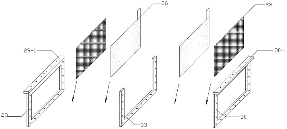
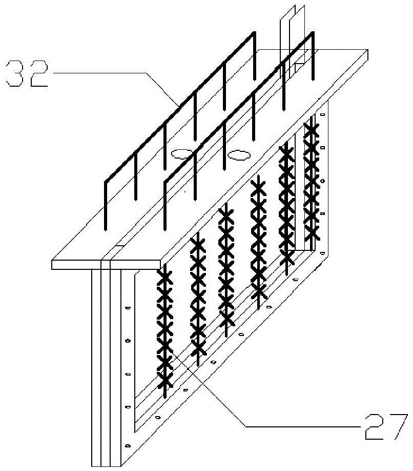
[0027]Embodiment 1: This embodiment is a stack baffle type microbial fuel cell including an open reaction box 1, a first microbial fuel cell 3, a second microbial fuel cell 5, a third microbial fuel cell 7, and a fourth microbial fuel cell Fuel cell 9, fifth microbial fuel cell 11, water inlet 2, water outlet 14, first socket 17, second socket 18, third socket 19, fourth socket 20, fifth socket 21, first water intake 4, The second water intake 6, the third water intake 8, the fourth water intake 10, the fifth water intake 12, the sixth water intake 13, the seventh water intake 15, the eighth water intake 22, the ninth water intake 23, the tenth water intake Water intake 24, eleventh water intake 25, water storage tank 34, water pump 35, high water tank 36, liquid flow meter 37 and sealing cover 16;
[0028] The left side wall of the open reaction box 1 is provided with a water inlet 2, the right side wall is provided with a water outlet 14 and the seventh water intake 15, and ...
specific Embodiment approach 2
[0047] Embodiment 2: The difference between this embodiment and Embodiment 1 is that the thickness of the U-shaped partition 33 can be adjusted, and the thickness is 0.8 cm to 1.2 cm. Others are the same as the first embodiment.
[0048] The U-shaped separator 33 is placed between the two cells in the microbial fuel cell to form air cavities of different volumes, and the thickness of the U-shaped separator 33 is adjusted so that the oxygen concentration will not limit the electron-consuming reaction of the cathode.
specific Embodiment approach 3
[0049] Embodiment 3: The difference between this embodiment and Embodiment 1 or 2 is that the first microbial fuel cell 3 is set at the first water intake 4 and the second water intake 6 inside the open reaction box 1 Between; the third microbial fuel cell 7 is arranged between the third water intake 8 and the fourth water intake 10 in the open reaction box 1; the fifth microbial fuel cell 11 is arranged in the first open reaction box 1 Between the fifth water intake 12 and the sixth water intake 13; the second microbial fuel cell 5 is arranged between the eighth water intake 22 and the ninth water intake 23 inside the open reaction box 1; the fourth microbial fuel cell 9 is arranged Between the tenth water intake 24 and the eleventh water intake 25 inside the open reaction box 1 . Others are the same as those in Embodiment 1 or 2.
[0050] This embodiment can indicate the removal trend of organic matter in the direction of water flow in the open reaction box 1 .
PUM
| Property | Measurement | Unit |
|---|---|---|
| thickness | aaaaa | aaaaa |
Abstract
Description
Claims
Application Information
 - R&D
- Intellectual Property
- Life Sciences
- Materials
- Tech Scout
- Unparalleled Data Quality
- Higher Quality Content
- 60% Fewer Hallucinations
Browse by: Latest US Patents, China's latest patents, Technical Efficacy Thesaurus, Application Domain, Technology Topic, Popular Technical Reports.
© 2025 PatSnap. All rights reserved.Legal|Privacy policy|Modern Slavery Act Transparency Statement|Sitemap|About US| Contact US: help@patsnap.com


